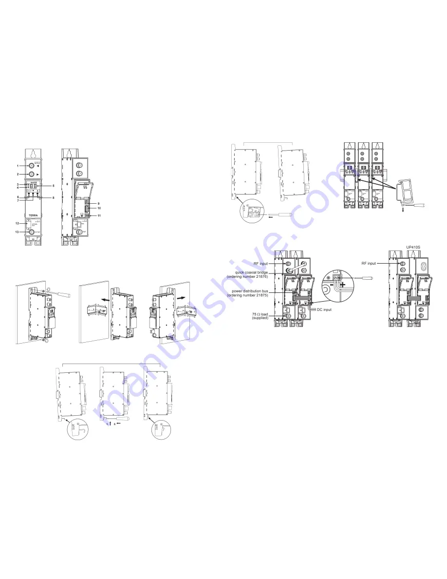
Installation instructions
Read the safety instruction first.
Connect the 75 Ω load to the unused F sockets.
MOUNTING
The module
or mounting bracket must be fixed with steel screws
Ø 3.5-4 mm. The screws are not included
in a package.
Mounting on a wall by screws
Mounting on a bracket (supplied)
Perpendicular to the wall
Parallel to the wall
Figure 2.
Mounting of the transmitter
1
- ◄ - RF input, DC 12 V switchable (F socket)
2
- ► - RF output (input signal loop-through) (F socket)
3
-
ADDR.
- indicator of the transmitter adressed
4
-
ST.
- LED indicator of the transmitter status
5
- LED display
6
-
SELECT
- control panel “select” button
7
- ▼ - control panel “down” button
8
- ▲ - control panel “up” button
9
- data bus connector (under the cover)
10
- power distribution bus connector (under the cover)
11
- +12 V powering input (screw terminal)
12
- optical output (SC/APC socket)
13
-
RF test point (F socket)
Figure 1.
External view of the transmitter
External view
Mounting on a DIN rail
Figure 3. Mounting to DIN rail
Figure 4. Mounting from DIN rail
Figure 5. Mounting or removing to/from
DIN rail of plastic spacers (supplied).
Connection of cables
Figure 6 a. Powering of transmitter
Figure 6 b. Powering of transmitter
via screw terminal block
via power distribution bus
OPERATING
Settings
Select parameter by pressing button
SELECT
.
Enter necessary parameter values by pressing ▲ and ▼ buttons:
[A1] RF attenuator: ▼ to decrease or ▲ to increase attenuator values (0…15 dB, step 1 dB)
[AL] AGC gain: ▼ OF - AGC is switched off;
▲ ON AGC is switched on.
Is used to set automatic RF level control for constant load to the laser:
The operating AGC level is determined by user at the moment on pressing ▲ button. After that, RF level instability is
compensated automatically by the internal attenuator. If attenuator can’t to compensate RF level, error diagnostic message
“E3” (No AGC) occurs:
[UE] to switch DC voltage on RF input socket: ▼ OF: 0V; ▲ ON: 12V
[rF] ▲ Indicates input RF signal average load power. It depends on input signals values and number of channels.
[L1] ▲ Indicates current of Laser 1;
[L2] ▲ Indicates current of Laser 2;
[U1] ▲ Indicates external voltage DC on RF input socket;
[U2] ▲ Indicates supply voltage 12V;
[U3] ▲ Indicates internal 5V supply voltage;
[tE] ▲ Indicates internal temperature of device;
Diagnostic warnings and errors:
E-
no warnings or errors (green color of status LED).
UP410S
- power supply


