


Page 20
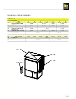
Assembly instructions - Standard duct
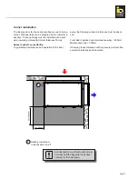
Air inlet side:
The inlet-side wall connection is supplied separately. Ver-
tical connections must be affixed first. To do this, simply
remove the film on the rear side. The cellular rubber can
then be affixed flush with the external edge of the heat
pump.
Additionaly the horizontal elements are also lined on the
front. This will help ensure an optimum seal.
Before the machine is positioned on the inlet opening,
check that the wall opening prepared by the customer
has been insulated.
The heat pump may only be moved with
the panels fitted.
If there are any air gaps on the outlet or inlet openings
due to the ground being uneven, this can be corrected
using the adjustable machine feet.
Significant pressure against the wall
should be avoided.
Outlet panels:
The outlet panel is mounted using the four clamps sup-
plied.
Duct:
Assemble the duct using the screw set supplied. The
fitting length should then be checked.
If the straight duct is too long, two rivets can be bored
open on one side so that the flange can be removed. The
duct can then be cut to length using an angle grinder or
a jigsaw with the relevant blade. The flange can then be
re-fitted.
Insulation:
The insulation for the straight duct is supplied separately.
This is self-adhesive and needs to be affixed once the
duct has been cut to the correct length.
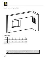
Wall connection:
The wall connection is sprayed into the wall opening with
assembly foam. The outlet duct must be connected befo-
re the foam hardens.
If two or more ducts are assembled
together, the duct must be supported
(above or below).


