background image

Service and Repair Manual


November 2020


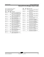
Fault Codes 


120 

Z

®

-45 XC


• Z

®

-45 HF


Part No. 1268197GT 


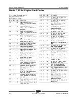
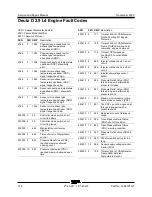
Code 

Description 

301 

Emissions/catalyst damaging misfire   

302 

Emissions/catalyst damaging misfire   

303 

Emissions/catalyst damaging misfire   

304 

Emissions/catalyst damaging misfire   

305 

Emissions/catalyst damaging misfire   

306 

Emissions/catalyst damaging misfire   

307 

Emissions/catalyst damaging misfire   

308 

Emissions/catalyst damaging misfire   

326 

Knock 1 Excessive Signal   

327 

Knock 1 sensor Open   

331 

Knock 2 Excessive Signal   

332 

Knock 2 sensor Open   

336 

Crank sync noise   

337 

Crank loss   

341 

Cam sync noise   

342 

Cam loss   

420 

Gasoline cat monitor   

430 

Gasoline cat monitor   

524 

Oil pressure low   

562 

Battery Voltage Low   

563 

Battery Voltage High   

601 

Flash checksum invalid   

604 

RAM failure   

606 

COP failure   

615 

Start relay coil open   

616 

Start relay control ground short   

617 

Start relay coil short to power   

627 

Fpump relay coil open   

628 

FPump motor loop open or high-side shorted 
to ground   

628 

Fpump relay control ground short   

629 

FPump motor high-side shorted to power   

629 

Fpump relay coil short to power   


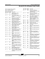
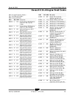
Code 

Description 

642 

5VE1 low voltage   

643 

5VE1 high voltage   

650 

MIL open   

652 

5VE2 low voltage   

653 

5VE2 high voltage   

685 

Relay Coil Open   

686 

Relay Control ground short   

687 

Relay coil short to power   

1111 

Fuel rev limit   

1112 

Spark rev limit   

1121 

FPP1/2 simultaneous voltages out of range 

1122 

FPP1/2 do not match each other or the IVS 

1151 

CL high LPG   

1152 

CL low LPG   

1153 

CL high NG   

1154 

CL low NG   

1155 

CL high gasoline bank1   

1156 

CL low gasoline bank1   

1157 

CL high gasoline bank2   

1158 

CL low gasoline bank2   

1161 

AL high LPG   

1162 

AL low LPG   

1163 

AL high NG   

1164 

AL low NG   

1165 

LPG cat monitor   

1166 

NG cat monitor   

1171 

Megajector delivery pressure higher than 
expected   

1172 

Megajector delivery pressure lower than 
expected   


Ford MSG-425 EFI Diagnostic Manual 

Genie part number 

162067GT 


Содержание Genie Z-45 XC

Страница 1: ...Z4525XCF 101 from Z4525XCM 101 This manual includes Repair procedures Fault Codes Electrical and Hydraulic Schematics Z 45 HF For detailed maintenance procedures refer to the appropriate Maintenance Manual for your machine Part No 1268197GT Rev E November 2020 ...

Страница 2: ... Life Unrestricted with proper operation inspection and scheduled maintenance Technical Publications Genie has endeavored to deliver the highest degree of accuracy possible However continuous improvement of our products is a Genie policy Therefore product specifications are subject to change without notice Readers are encouraged to notify Genie of errors and send in suggestions for improvement All...

Страница 3: ...Platform Overload Fault Codes Schematics Hour Meter Pin Legend B 9 2017 Schematics Add wiring diagrams B1 11 2017 Specifications Machine Specifications B2 6 2018 Schematics GCON Terminal Strip Wiring Diagram C 1 2019 Specifications Added ANSI CSA engines Schematics Added ANSI CSA Schematics D 10 2019 Specifications Machine Specifications Repair Procedure 2 3 E 11 2020 All Sections Add Deutz TD 2 2...

Страница 4: ...injury Many of the hazards identified in the operator s manual are also safety hazards when maintenance and repair procedures are performed Do Not Perform Maintenance Unless You are trained and qualified to perform maintenance on this machine You read understand and obey manufacturer s instructions and safety rules employer s safety rules and worksite regulations applicable governmental regulation...

Страница 5: ...l crushing hazards such as moving parts free swinging or unsecured components when lifting or placing loads Always wear approved steel toed shoes Workplace Safety Any person working on or around a machine must be aware of all known safety hazards Personal safety and the continued safe operation of the machine should be your top priority Be sure to keep sparks flames and lighted tobacco away from f...

Страница 6: ...pecifications 1 Performance Specifications 2 Hydraulic Oil Specifications 2 Hydraulic Component Specifications 5 Deutz D 2 9 L4 Engine Specifications 7 Deutz TD 2 2 L3 Engine Specifications 8 Deutz D2011 L03i Engine Specifications 9 Perkins 404D 22 Engine Specifications 10 Perkins 404F E22T Engine Specifications 11 Ford MSG 425 EFI Engine Specifications 12 Machine Torque Specifications 13 Hydrauli...

Страница 7: ... Cylinder 25 2 2 Platform Rotator 25 2 3 Platform Overload System 26 How to Replace the Platform Overload Load Cell 29 2 4 Platform Overload Recovery Fault 29 Jib Boom Components 30 3 1 Jib Boom 30 3 2 Jib Boom Lift Cylinder 31 Primary Boom Components 33 4 1 Cable Track 33 How to Remove the Cable Track 33 How to Repair the Primary Boom Cable Track 35 4 2 Primary Boom 35 How to Disassemble the Prim...

Страница 8: ...old Components ANSI CSA CE from Z4525XCF 101 Z4525XCM 1501 59 8 2 Valve Adjustments Function Manifold 64 How to Adjust the System Relief Valve 64 How to Adjust the Secondary Boom Down Relief Valve 64 8 3 Jib Boom Platform Rotate Manifold Components 65 8 4 Turntable Rotation Manifold Components 66 8 5 Directional Valve Manifold Components 67 How to Set Up the Directional Valve Linkage 68 8 6 Tracti...

Страница 9: ... L4 and Perkins 404F E22T Models 87 How to Retrieve Active Engine Fault Codes Deutz TD 2 2 L3 Models 88 Fault Code Display Flashing and Solid LED s Deutz D 2 9 L4 and Perkins 404F E22T Models 89 Soft Key Functions and Icons Deutz D 2 9 L4 and Perkins 404F E22T Models 90 Soft Key Functions and Icons Deutz TD 2 2 L3 Models 91 Main Menu Structure Deutz D 2 9 L4 Models 92 Main Menu Structure Deutz TD ...

Страница 10: ...ical Schematic Deutz D2011L03i and Perkins 404D 22 133 Electrical Schematic Deutz D 2 9 L4 136 Engine Wire Harness Deutz D 2 9 L4 137 Electrical Schematic Deutz TD 2 2 L3 140 Engine Wire Harness Deutz TD 2 2 L3 Page 1 141 Engine Wire Harness Deutz TD 2 2 L3 Page 2 143 Electrical Schematic Perkins 404F 22T 146 Perkins 404F E22T Engine Wire Harness 147 Electrical Schematic Function Controls ANSI CSA...

Страница 11: ...kins 404F E22T ANSI CSA 163 Ground Control Box Switch Panel Wiring Diagram Ford MSG425 ANSI CSA 166 Ground Control Box Terminal Strip Wiring Diagram Ford MSG425 ANSI CSA 167 Ground Control Box Switch Panel Wiring Diagram CE 170 Ground Control Box Terminal Strip Wiring Diagram CE 171 Platform Control Box Switch Panel Wiring Diagram 174 Platform Control Box Terminal Strip Wiring Diagram 175 Platform...

Страница 12: ...Service and Repair Manual November 2020 12 Z 45 XC Z 45 HF Part No 1268197GT This page intentionally left blank ...

Страница 13: ...145 lbs 66 kg Overall tire diameter 33 in 88 8 cm Wheel diameter 19 5 in 49 5 Wheel width 14 in 35 5 Tire pressure 38 psi 2 62 bar Wheel lugs 9 5 8 18 Lug nut torque lubricated 94 ft lbs 127 4 Nm Lug nut torque dry 125 ft lbs 169 5 Nm Fuel capacities LPG tank 33 5 pounds 15 2 kg Fuel tank 17 gallons 64 4 liters Hydraulic tank 22 gallons 83 liters Hydraulic system including tank 30 gallons 113 6 li...

Страница 14: ...the ability to perform over a wide temperature range and the viscosity index should exceed 140 They should provide excellent antiwear oxidation prevention corrosion inhibition seal conditioning and foam and aeration suppression properties Cleanliness level minimum ISO 15 13 Water content maximum 250 ppm Recommended Hydraulic Fluid Hydraulic oil type Chevron Rando HD Premium Viscosity grade 32 Visc...

Страница 15: ... 120 F 49 C Hydraulic Fluid Temperature Range Ambient air temperature 1 Chevron hydraulic oil 5606A 2 Petro Canada Environ MV 46 3 UCON Hydrolube HP 5046D 4 Chevron Rando HD premium oil MV Chevron Rando HD Premium Oil MV Fluid Properties ISO Grade 32 Viscosity index 200 Kinematic Viscosity cSt 200 F 100 C cSt 104 F 40 C 7 5 33 5 Brookfield Viscosity cP 4 F 20 C cP 22 F 30 C 1040 3310 Flash point 3...

Страница 16: ... system is used Continued use of Chevron 5606A hydraulic fluid or equivalent when ambient temperatures are consistently above 32 F 0 C may result in component damage Petro Canada Environ MV 46 Fluid Properties ISO Grade 46 Viscosity index 154 Kinematic Viscosity cSt 200 F 100 C cSt 104 F 40 C 8 0 44 4 Flash point 482 F 250 C Pour point 49 F 45 C Maximum continuous operating temperature 180 F 82 C ...

Страница 17: ... Drive Pump Type bi directional variable displacement piston pump Flow rate 2500 psi 172 bar 32 gpm 121 L min Drive pressure maximum 3500 psi 241 bar Charge Pump Type gear Displacement per revolution 0 84 cu in 13 76 cc Flow rate 2500 psi 172 bar 9 1 gpm 34 4 L min Charge pressure 2500 rpm 315 psi 21 7 bar Function Pump Type gear Displacement per revolution 0 67 cu in 11 cc Flow rate 2500 psi 172 ...

Страница 18: ...7 2 bar Steer end drive motors Displacement per revolution variable 0 54 to 1 53 cu in 8 77 to 25 cc Non steer end drive motors Displacement per revolution variable 2 speed motor 0 54 to 1 53 cu in 8 85 to 25 1 cc Hydraulic Filters High pressure filter Beta 3 ˆ 200 High pressure filter bypass pressure 102 psi 7 bar Medium pressure filter Beta 3 ˆ 200 Medium pressure filter bypass pressure 51 psi 3...

Страница 19: ...0 Above 23 F 5 C 20W 50 Unit ships with 15W 40 Extreme operating temperatures may require the use of alternative engine oils For oil requirements refer to the Engine Operator Manual for your engine Oil temperature switch Temperature switch point 257 F 125 C Oil Pressure switch Oil pressure switch point 20 psi 1 4 bar Engine coolant Capacity 10 quarts 9 4 liters Fuel injection system Injection pump...

Страница 20: ...ips with 15W 40 Extreme operating temperatures may require the use of alternative engine oils For oil requirements refer to the Engine Operator Manual for your engine Oil temperature switch Installation torque 8 18 ft lbs 11 24 Nm Temperature switch point 257 F 125 C Oil Pressure switch Installation torque 8 18 ft lbs 11 24 Nm Pressure switch point 17 4 psi 1 2 bar Fuel requirement For fuel requir...

Страница 21: ...tic 4 F to 90 F 20 C to 32 C 10W 40 Above 23 F 5 C 20W 50 Unit ships with 15W 40 Extreme operating temperatures may require the use of alternative engine oils For oil requirements refer to the Engine Operator Manual for your engine Oil temperature switch Temperature switch point 300 F 149 C Oil Pressure switch Oil pressure switch point 22 psi 1 5 bar Fuel injection system Injection pump make Bosch...

Страница 22: ...osity requirements Below 86 F 30 C 5W 20 4 F to 104 F 20 C to 40 C 10W 30 Above 14 F 10 C 15W 40 Unit ships with 15W 40 Extreme operating temperatures may require the use of alternative engine oils For oil requirements refer to the Engine Operator Manual for your engine Oil pressure sending unit Oil pressure switch point 14 2 psi 1 bar Fuel injection system Injection pump make Zexel Injection pres...

Страница 23: ...viscosity requirements Below 86 F 30 C 5W 20 4 F to 104 F 20 C to 40 C 10W 30 Above 14 F 10 C 15W 40 Unit ships with 15W 40 Extreme operating temperatures may require the use of alternative engine oils For oil requirements refer to the Engine Operator Manual for your engine Oil pressure sending unit Oil pressure switch point 14 2 psi 1 bar Fuel injection system Injection pump make Zexel Injection ...

Страница 24: ...re switch point 7 5 psi 0 51 bar Oil viscosity requirements Extreme operating temperatures may require the use of alternative engine oils For oil requirements refer to the Engine Operator Handbook on your machine Electronic fuel pump Fuel pressure static 60 psi 4 1 bar Fuel flow rate 0 58 gpm 2 2 L min Fuel requirement For fuel requirements refer to the engine Operator Manual for your engine Ignit...

Страница 25: ... Nm Hydraulic Hose and Fitting Torque Specifications Your machine is equipped with Parker Seal Lok ORFS or 37 JIC fittings and hose ends Genie specifications require that fittings and hose ends be torqued to specification when they are removed and installed or when new hoses or fittings are installed Seal Lok Fittings hose end ORFS SAE Dash Size Torque 4 18 ft lbs 25 Nm 6 30 ft lbs 41 Nm 8 40 ft l...

Страница 26: ...able Fitting Non adjustable fitting 1 jam nut SAE O ring Boss Port tube fitting installed into Steel SAE Dash Size Torque 4 ORFS 37 Adj ORFS Non adj 37 Non adj 15 ft lbs 20 3 Nm 26 ft lbs 35 3 Nm 22 ft lbs 30 Nm 6 ORFS Adj Non adj 37 Adj Non adj 35 ft lbs 47 5 Nm 29 ft lbs 39 3 Nm 8 ORFS Adj Non adj 37 Adj Non adj 60 ft lbs 81 3 Nm 52 ft lbs 70 5 Nm 10 ORFS Adj Non adj 37 Adj Non adj 100 ft lbs 13...

Страница 27: ...custom size O rings They are not standard size O rings They are available in the O ring field service kit Genie part number 49612GT 2 Lubricate the O ring before installation 3 Be sure the O ring face seal is seated and retained properly 4 Position the tube and nut squarely on the face seal end of the fitting and tighten the nut finger tight 5 Tighten the nut or fitting to the appropriate torque R...

Страница 28: ... on the body hex fitting make a second mark with a permanent ink marker to indicate the proper tightening position Refer to Illustration 2 Note Use the JIC 37 Fitting table in this section to determine the correct number of flats for the proper tightening position Note The marks indicate the correct tightening positions have been determined Use the second mark on the body hex fitting to properly t...

Страница 29: ...al on your machine Be sure that all necessary tools and parts are available and ready for use Use only Genie approved replacement parts Read each procedure completely and adhere to the instructions Attempting shortcuts may produce hazardous conditions Machine Configuration Unless otherwise specified perform each repair procedure with the machine in the following configuration Machine parked on a f...

Страница 30: ... alert personnel to potential personal injury hazards Obey all safety messages that follow this symbol to avoid possible injury or death Indicates a imminently hazardous situation which if not avoided will result in death or serious injury Indicates a potentially hazardous situation which if not avoided could result in death or serious injury Indicates a potentially hazardous situation which if no...

Страница 31: ...oystick controller 1 1 ALC 500 Circuit Board Note When the ALC 500 circuit board is replaced the joystick controllers will need to be calibrated Refer to Repair Procedure How to Calibrate a Joystick How to Remove the ALC 500 Circuit Board 1 Push in the red Emergency Stop button to the off position at both the ground and platform controls 2 Remove the platform control box lid retaining fasteners Op...

Страница 32: ...ons or replace the joystick 8 Repeat this procedure for each joystick controlled machine function including the thumb rocker steer switch Note No machine function should operate while performing the joystick calibration procedure How to Adj ust the Joystick Max out Setting How to Adjust the Joystick Max out Setting The max out setting of a joystick controls the maximum speed of a joystick controll...

Страница 33: ...ximately 10 seconds to allow the settings to be saved Result The alarm should sound indicating that the settings have been saved in memory Note Do not operate any machine function during the 10 second waiting time How to Adj ust the Joystick Ramp R ate Setting How to Adjust the Joystick Ramp Rate Setting The ramp rate setting of a joystick controls the time at which it takes for the joystick to re...

Страница 34: ... the drive enable toggle switch is momentarily moved the time will change in 10 increments 12 Repeat steps 9 through 11 for each joystick controlled machine function 13 Return the joystick to the neutral position and wait for approximately 10 seconds to allow the settings to be saved Result The alarm should sound indicating that the settings have been saved in memory Note Do not operate any machin...

Страница 35: ...nd the alarm should sound 8 times indicating that the machine is in threshold calibration mode Result The alarm does not sound Repeat steps 3 through 7 8 Start the engine from the platform controls and press down the foot switch 9 Select a boom function joystick to set the threshold 10 Slowly move the joystick off center in either direction just until the function begins to move 11 Slowly move the...

Страница 36: ...upport 3 Lower the primary boom until the platform is resting on the blocks just enough to support the platform Note Do not rest the entire weight of the boom on the blocks 4 Tag disconnect and plug the hydraulic hoses from the slave cylinder at the unions and connect them together using a connector Connect the hoses from the cylinder together using a connector Bodily injury hazard Spraying hydrau...

Страница 37: ...tion enable toggle switch to either side and activate the platform rotate toggle switch to the right then the left through two platform rotation cycles then hold the switch to the right position until the platform is fully rotated to the right 2 Place a suitable container underneath the platform rotator 3 Open the top bleed screw on the rotator but do not remove it Bodily injury hazard Spraying hy...

Страница 38: ...rated platform overload system could result in the system failing to sense an overloaded platform The stability of the machine is compromised and it could tip over Note Perform this procedure with the machine on a firm level surface How to Perform a Zero Load Platform Calibration Perform this procedure when platform overload is not operating within the calibration parameters This procedure will re...

Страница 39: ...en replaced or if a zero load platform calibration does not return the machine to full load capacity 1 Remove all weight tools accessories and equipment from the platform Note Remove the welder if equipped Tip over hazard Failure to remove all non integrated factory and non factory options and accessories could result in the machine tipping over causing death or serious injury 2 Turn the key switc...

Страница 40: ... or ratchet 4 anchoring device 6 Activate and hold the calibration toggle switch in the up position for 2 seconds to store the rated load calibration Result An audible alarm sounds for 1 second Calibration has been stored 7 Push in the red Emergency Stop button to the off position Confirm calibration 8 Start the engine from the ground controls 9 Place an additional 50 lbs 23 kg of weight in the pl...

Страница 41: ...tighten the two mounting screws Torque the bolts to 101 ft lbs 137 Nm Set the Load Cell Sensor Preload 8 Rotate the foot screw counter clockwise until the foot just contacts the flex plate finger tight 9 Using an open end wrench continue to rotate the foot counter clockwise an additional 1 2 turn 180 Then while holding the foot bolt securely tighten the jam nut Torque the jam nut to 55 ft lbs 75 N...

Страница 42: ... to squirt or spray 4 Remove the platform mounting weldment 5 Attach a lifting strap from an overhead crane to the platform rotator for support 6 Remove the pin retaining fastener from the jib boom lift cylinder rod end pivot pin Do not remove the pin 7 Remove the pin retaining fasteners from both platform rotator pivot pins Do not remove the pins 8 Use a soft metal drift to remove the leveling ar...

Страница 43: ...ced and fall when it is removed from the machine if it is not properly supported by the overhead crane 3 2 Jib Boom Lift Cylinder How to Remove the Jib Boom Lift Cylinder Note Perform this procedure with the boom in the stowed position Note When removing a hose assembly or fitting the O ring if equipped on the fitting and or hose end must be replaced All connections must be torqued to specificatio...

Страница 44: ...d pivot pin 7 Use a soft metal drift to remove the pin and let the cylinder hang down Remove the platform rotator from the machine Crushing hazard The jib boom may become unbalanced and fall when it is removed from the machine if it is not properly supported by the overhead crane 8 Attach a lifting strap from an overhead crane to the lug on the rod end of the jib boom lift cylinder 9 Use a soft me...

Страница 45: ...Remove the hose clamp on the primary boom bellcrank 5 Pull all of the electrical cables out of the plastic cable track Do not pull out the hydraulic hoses 6 Tag disconnect and plug the hydraulic hoses from the V1 and V2 ports on the counterbalance valve manifold located on the platform rotator Cap the fittings on the manifold Bodily injury hazard Spraying hydraulic oil can penetrate and burn skin ...

Страница 46: ...de of the primary boom 15 Support the rod end of the primary boom lift cylinder with a suitable lifting device 16 Remove the pin retaining fasteners from the primary boom lift cylinder rod end pivot pin Do not remove the pin 17 Raise the primary boom slightly with the overhead crane to relieve the pressure on the primary boom lift cylinder rod end pivot pin 18 Use a soft metal drift to remove the ...

Страница 47: ...zard This procedure requires specific repair skills lifting equipment and a suitable workshop Attempting this procedure without these skills and tools could result in death or serious injury and significant component damage Dealer service is strongly recommended Note Perform this procedure with the boom in the stowed position Note When removing a hose assembly or fitting the O ring if equipped on ...

Страница 48: ...ly injury hazard Spraying hydraulic oil can penetrate and burn skin Loosen hydraulic connections very slowly to allow the oil pressure to dissipate gradually Do not allow oil to squirt or spray 13 Remove the hose clamp at the pivot end of the boom 14 Attach a 5 ton 5 000 kg overhead crane to the center point of the primary boom 15 Attach a similar lifting device to the primary boom lift cylinder 1...

Страница 49: ... from the platform end of the primary boom Note Pay careful attention to the location and amount of shims used with each wear pad 5 Support and slide the extension tube and extension cylinder assembly out of the boom tube Crushing hazard The primary boom extension tube could become unbalanced and fall when removed from the primary boom tube if not properly supported Note During removal the overhea...

Страница 50: ...take the pressure off the primary boom lift cylinder pivot pins 5 Support the rod end and the barrel end of the primary boom lift cylinder with a second overhead crane or similar lifting device 6 Tag disconnect and plug the primary boom lift cylinder hydraulic hoses Cap the fittings on the cylinder Bodily injury hazard Spraying hydraulic oil can penetrate and burn skin Loosen hydraulic connections...

Страница 51: ...d pivot pin is accessible in the primary boom extension tube 3 Remove the hose and cable guard from the upper pivot 4 Tag disconnect and plug the primary boom extension cylinder hydraulic hoses Cap the fittings on the cylinder Bodily injury hazard Spraying hydraulic oil can penetrate and burn skin Loosen hydraulic connections very slowly to allow the oil pressure to dissipate gradually Do not allo...

Страница 52: ...dary booms until both the rod end and barrel end pivot pins on the master cylinder are accessible 2 Tag disconnect and plug the master cylinder hydraulic hoses Cap the fittings on the cylinder Bodily injury hazard Spraying hydraulic oil can penetrate and burn skin Loosen hydraulic connections very slowly to allow the oil pressure to dissipate gradually Do not allow oil to squirt or spray 3 Attach ...

Страница 53: ...o 1268197GT Z 45 XC Z 45 HF 41 Secondary Boom components 1 upper secondary boom number 1 arm 2 upper tension link number 2 arm 3 lower tension link number 3 arm 4 mid pivot 5 compression link 6 secondary boom lift cylinder 2 7 lower secondary boom number 4 arm 8 upper pivot ...

Страница 54: ...he Master Cylinder 5 Attach a lifting strap from an overhead crane to the lug on the rod end of the primary boom lift cylinder Then raise the primary boom lift cylinder with the crane to a vertical position 6 Tag disconnect and plug the hydraulic hoses at the primary boom lift cylinder Cap the fittings on the cylinder Bodily injury hazard Spraying hydraulic oil can penetrate and burn skin Loosen h...

Страница 55: ... number 1 arm pivot pins at the mid pivot and the upper pivot Do not remove the pins 19 Use a soft metal drift to drive both pins out 20 Remove the number 1 arm from the machine Crushing hazard The number 1 arm could become unbalanced and fall when removed from the machine if not properly attached to the overhead crane Crushing hazard The upper pivot could fall when the number 1 arm is removed fro...

Страница 56: ... lifting strap from an overhead crane to the center point of the number 2 arm for support Do not lift it 36 Remove the pin retaining fasteners from both compression link pivot pins Do not remove the pins 37 Use a soft metal drift to remove the lower compression link pivot pin at the number 3 arm 38 Support the compression link with an appropriate lifting device 39 Use a soft metal drift to remove ...

Страница 57: ...pin 50 Attach the lifting strap from the overhead crane to the center point of the number 3 arm for support Do not lift it 51 Remove the mounting fasteners from the cover located in the boom storage area to access the number 3 and number 4 arm pivot pin retaining fasteners at the turntable riser 52 Remove the pin retaining fasteners from the number 3 arm at the turntable riser Do not remove the pi...

Страница 58: ...towed position 2 Raise the primary boom so that it is above the secondary boom lift cylinder rod end pivot pin 3 Tag disconnect and plug the hydraulic hoses on the secondary boom lift cylinder Bodily injury hazard Spraying hydraulic oil can penetrate and burn skin Loosen hydraulic connections very slowly to allow the oil pressure to dissipate gradually Do not allow oil to squirt or spray 4 Remove ...

Страница 59: ...onnect the battery cables from the battery Electrocution burn hazard Contact with electrically charged circuits could result in death or serious injury Remove all rings watches and other jewelry 2 Disconnect the electrical connectors at the electrical proportional controller located on the drive pump 3 Remove the engine starter mounting fasteners Remove the starter from the engine Do not disconnec...

Страница 60: ...d Hoses can be damaged if they are kinked or pinched 6 Disconnect the electrical connector from the oxygen sensor at the tailpipe Do not remove the oxygen sensor 7 Support the muffler and bracket assembly with a suitable lifting device 8 Remove the exhaust pipe fasteners at the muffler 9 Remove the muffler bracket mounting fasteners from the bell housing Carefully remove the muffler and bracket as...

Страница 61: ...eners 3 Deutz models Torque the flex plate mounting bolts in sequence to 28 ft lbs 38 Nm Then torque the flex plate mounting bolts in sequence to 40 ft lbs 54 Nm Ford and Perkins models Torque the flex plate mounting bolts in sequence to 14 ft lbs 19 Nm Then torque the flex plate mounting bolts in sequence to 20 ft lbs 27 Nm 4 Apply a high viscosity coupling grease Genie part number 128025 to the ...

Страница 62: ... 66 Nm Then torque the bell housing mounting bolts labeled A and B in sequence to 40 ft lbs 54 Nm and the mounting bolts labeled C to 70 ft lbs 95 Nm Perkins models Torque the bell housing mounting bolts labeled B in sequence to 28 ft lbs 38 Nm and the mounting bolts labeled A to 49 ft lbs 66 Nm Then torque the bell housing mounting bolts labeled B in sequence to 40 ft lbs 54 Nm and the mounting b...

Страница 63: ...ntial fuel injection and make constant and instantaneous changes to ignition timing fuel delivery and throttle position to maintain the engine s running condition at its highest efficiency while at the same time keeping exhaust emissions to a minimum When a sensor fails or returns signals that are outside of set parameters the ECM will store a fault code in memory that relates to the appropriate s...

Страница 64: ...any actions Standstill regeneration If passive regeneration does not attain an adequate reduction of the soot contamination the particle filter will continue to become contaminated with soot and a standstill regeneration will be required by the operator To perform standstill regeneration refer to the Operator s Manual on your machine Service regeneration If a fault occurs the system reacts by redu...

Страница 65: ...nent damage hazard The engine must not be started with the hydraulic tank shut off valves in the closed position or component damage will occur If the tank valves are closed remove the key from the key switch and tag the machine to inform personnel of the condition open closed 2 Tag disconnect and plug the lift steer pump hydraulic hoses Cap the fittings on the pump Bodily injury hazard Spraying h...

Страница 66: ...d must be replaced All connections must be torqued to specification during installation Refer to Specifications Hydraulic Hose and Fitting Torque Specifications 1 Disconnect the electrical connectors at the electrical proportional controller located on the drive pump 2 Locate the two hydraulic tank valves at the hydraulic tank through the access hole underneath the turntable Close the valves Compo...

Страница 67: ...ump How to Prime the Pump 1 Connect a 0 to 600 psi 0 to 41 bar pressure gauge to the test port on the drive pump 2 Remove the safety pin from the engine pivot plate latch Note The engine pivot plate latch is located under the engine turntable pivot plate at the counterweight end of the machine 3 Open the engine pivot plate latch and swing the engine pivot plate out and away from the machine 4 Hold...

Страница 68: ... psi 11 bar BG Meters flow to functions 25 ft lbs 34 Nm 7 Proportional directional solenoid valve 3 position 4 way BP Turntable rotate left right 16 20 ft lbs 22 27 Nm 8 Proportional directional solenoid valve 3 position 4 way BU Secondary boom up down 16 20 ft lbs 22 27 Nm 9 Solenoid valve 3 position 4 way BF Steer left right 25 ft lbs 34 Nm 10 Relief valve 2100 psi 145 bar BV Secondary boom down...

Страница 69: ...November 2020 Service and Repair Manual Manifolds Part No 1268197GT Z 45 XC Z 45 HF 57 ...

Страница 70: ...e valve 3000 psi 207 bar CD Primary boom down circuit 30 35 ft lbs 45 50 Nm 24 Pressure compensator valve 80 psi 5 5 bar BR Turntable rotate circuit 25 ft lbs 34 Nm 25 Shuttle valve CE Differential sensing circuit primary boom up down 12 14 ft lbs 16 19 Nm 26 Flow regulator valve 0 8 gpm 3 L min BE Jib boom and platform rotate circuit 20 ft lbs 27 Nm 27 Needle valve BN Platform level flow control ...

Страница 71: ...November 2020 Service and Repair Manual Manifolds Part No 1268197GT Z 45 XC Z 45 HF 59 ...

Страница 72: ...CK 4 SAE 5 PSI CB Differential sensing circuit primary boom retract 12 14 ft lbs 16 19 Nm 7 VALVE RELIEF RV08 22H 0 N 26 21 BV Secondary boom down 20 ft lbs 27 Nm 8 VALVE SOLENOID 2POS 3 WAY CA Primary boom extend 20 ft lbs 27 Nm 9 VALVE PROPORTIONAL 3 POS 4 WY BY Primary boom up down 16 20 ft lbs 22 27 Nm 10 VALVE SPOOL 4 WAY 3 POSITION BP Turntable rotate left right 16 20 ft lbs 22 27 Nm 11 VALV...

Страница 73: ...November 2020 Service and Repair Manual Manifolds Part No 1268197GT Z 45 XC Z 45 HF 61 ...

Страница 74: ...Platform level flow control 20 ft lbs 27 Nm 26 VALVE PRESSURE REDUCER PR58 38H 0 N 05 05 CJ Oscillate circuit pressure reducing valve 24 26 ft lbs 33 35 Nm 27 VALVE RELIEF RV08 22H 0 N 26 35 BH Platform level circuit 20 ft lbs 27 Nm 28 VALVE PRESSURE CONTROL PS10 41H 0 N 22 08 5 CK Oscillate circuit pressure control valve 25 ft lbs 34 Nm 29 VALVE SOLENOID 2POS 3 WAY CC Primary boom retract 20 ft l...

Страница 75: ...November 2020 Service and Repair Manual Manifolds Part No 1268197GT Z 45 XC Z 45 HF 63 ...

Страница 76: ...Do not adjust the relief valve higher than specified 7 Repeat steps 2 through 5 and recheck relief valve pressure 8 Remove the pressure gauge How to Adj ust the Secondary Boom D own Relief Val ve How to Adjust the Secondary Boom Down Relief Valve Note Perform this procedure with the boom in the stowed position Note Refer to Function Manifold Component list to locate the secondary boom down relief ...

Страница 77: ...C Z 45 HF 65 8 3 Jib Boom Platform Rotate Manifold Components The jib boom platform rotate manifold is mounted to the platform support Index No Description Schematic Item Function Torque 1 Solenoid valve 2 position 3 way G Platform rotate jib boom select 8 10 ft lbs 11 14 Nm ...

Страница 78: ...Turntable Rotation Manifold Components The turntable rotation manifold is mounted to the turntable rotation motor located in the boom storage compartment Index No Description Schematic Item Function 1 Counterbalance valve L Turntable rotate right 2 Counterbalance valve J Turntable rotate left ...

Страница 79: ...45 XC Z 45 HF 67 8 5 Directional Valve Manifold Components The directional valve manifold is mounted inside the drive chassis at the non steer end Index No Description Schematic Item Function Torque 1 Cap Breather 20 25 ft lbs 27 33 Nm 2 Spool valve CH Directional control ...

Страница 80: ...ive chassis cover and the non steer axle covers 5 Place a bubble type level across the drive chassis non steer end Check to be sure the drive chassis is completely level 6 Remove the ball joint retaining fastener from the bracket 7 To level the drive chassis start the engine and push up or pull down on the threaded rod until the machine is completely level 8 Verify that the ground and drive chassi...

Страница 81: ...November 2020 Service and Repair Manual Part No 1268197GT Z 45 XC Z 45 HF 69 This page intentionally left blank ...

Страница 82: ... 7 Solenoid valve 2 position 3 way AG Braking 10 12 ft lbs 14 16 Nm 8 Relief valve 250 psi 17 2 bar AH Charge pressure circuit 10 12 ft lbs 14 16 Nm 9 Solenoid valve 2 position 3 way AI 2 speed motor shift 10 12 ft lbs 14 16 Nm 10 Check valve AJ Steer end drive motor circuit 10 12 ft lbs 14 16 Nm 11 Check valve AK Steer end drive motor circuit 10 12 ft lbs 14 16 Nm 12 Check valve AL Non steer end ...

Страница 83: ...November 2020 Service and Repair Manual Manifolds Part No 1268197GT Z 45 XC Z 45 HF 71 ...

Страница 84: ...he function enable rpm select toggle switch to the high rpm rabbit symbol position Note the reading on the pressure gauge 5 Turn the engine off 6 Remove the pressure gauge from the drive pump Connect the gauge to the test port located on the traction manifold 7 Hold the charge pressure relief valve and remove the cap 8 Start the engine and move and hold the function enable rpm select toggle switch...

Страница 85: ...ifold Components 2 2kW The generator manifold is mounted to the hydraulic generator located in the engine compartment Index No Description Schematic Item Function Torque 1 Proportional solenoid valve HH Generator speed 33 37 ft lbs 45 50 Nm 2 Relief valve 3000 psi 207 bar GG Generator circuit 20 25 ft lbs 27 34 Nm ...

Страница 86: ...on Schematic Item Function Torque 1 Relief valve GA Generator relief valve 50 ft lbs 67 Nm 2 Solenoid Valve GB Charge pressure circuit 60 65 ft lbs 81 88 Nm 3 Needle valve GD Charge pressure circuit 50 ft lbs 67 Nm 4 Differential sensing valve GC Pilot valve to diverter valve 50 ft lbs 67 Nm 5 Counterbalance valve GF Adds backpressure to generator circuit 6 Check valve GE Prevents oil to generator...

Страница 87: ...3 position 4 way directional valve 10V DC 6 to 8Ω schematic items BF BM and CG 2 position 3 way solenoid valve 10V DC 6 to 8Ω schematic items CA CC AF AG and AI How to Test a Coil Di ode How to Test a Coil Diode Properly functioning coil diodes protect the electrical circuit by suppressing voltage spikes Voltage spikes naturally occur within a function circuit following the interruption of electri...

Страница 88: ... lead to the other terminal on the coil 5 Momentarily connect the positive lead from the multimeter to the positive terminal on the 9V DC battery Note and record the current reading 6 At the battery or coil terminals reverse the connections Note and record the current reading Result Both current readings are greater than 0 mA and are different by a minimum of 20 The coil is good Result If one or b...

Страница 89: ...pivot plate at the counterweight end of the machine 4 Remove the center turntable cover retaining fasteners Remove the center turntable cover from the machine 5 Open the engine pivot plate latch and swing the engine pivot plate out and away from the machine 6 Tag disconnect and plug the hydraulic hoses from the turntable rotation motor manifold Cap the fittings on the manifold Bodily injury hazard...

Страница 90: ... Refer to Specifications Hydraulic Hose and Fitting Torque Specifications 1 Tag disconnect and plug the oscillating axle cylinder hydraulic hoses Cap the fittings on the oscillate cylinder Bodily injury hazard Spraying hydraulic oil can penetrate and burn skin Loosen hydraulic connections very slowly to allow the oil pressure to dissipate gradually Do not allow oil to squirt or spray 2 Remove the ...

Страница 91: ... sure that all necessary tools and test equipment are available and ready for use Read each appropriate fault code thoroughly Attempting short cuts may produce hazardous conditions Be aware of the following hazards and follow generally accepted safe workshop practices Electrocution burn hazard Contact with electrically charged circuits could result in death or serious injury Remove all rings watch...

Страница 92: ... hazard Electrostatic discharge ESD can damage printed circuit board components Maintain firm contact with a metal part of the machine that is grounded at all times when handling printed circuit boards OR use a grounded wrist strap 3 Determine the error source The red LED indicates the error source and will flash two separate codes The first code will indicate the first digit of the two digit code...

Страница 93: ... 17 Not Calibrated Normal function except threshold for one or both directions is zero Calibrate valve threshold 18 Just calibrated Initiate 1 second beep of Alarm Self clearing transient 24 Angle sensor 11 Value at 5 0 V Reduced function speed Retract before lowering required Dual capacity models Power up controller with problem corrected 12 Value too high 15 Value too low 16 Value at 0 V 17 Not ...

Страница 94: ... V Limited Speed and Direction frozen at zero and neutral Alarm sounds Power up controller with problem corrected 12 Value too high 15 Value too low 16 Value at 0 V 17 Not Calibrated Initiate 1 second beep of Alarm Calibrate Joystick 18 Just calibrated Initiate 1 second beep of Alarm Self clearing transient 42 Turntable Rotate Directional Valves 21 Fault Limited Speed and Direction frozen at zero ...

Страница 95: ...oller with problem corrected 55 Propel High Motor Speed Valve 21 Fault Motor speed frozen in the low state Power up controller with problem corrected 56 Platform Level Valve 21 Fault Direction frozen at zero and neutral Power up controller with problem corrected 57 Foot switch ECU Power Crosscheck 12 Value too high Direction frozen at zero and neutral Power up controller with problem corrected 15 ...

Страница 96: ...s At least one or more fault codes are present when the alarm at the platform and ground controls produces one short beep every second and a solid or flashing red LED is displayed on the hour meter at the ground controls The last two digits of the fault code are the Error Type The first two or three digits of the fault code are the Error Source 1 LCD display 2 red LED fault indicator 3 yellow LED ...

Страница 97: ... high Platform overloaded Reduce weight in platform 13 No Response No communication to load cell Check CAN bus circuit for open or short Check for cable damage to load cell Check for power at load cell 15 Value too low Output from load cell lower than expected while primary up is active Confirm the platform load cell is properly pre loaded and is free of obstructions 17 Not Calibrated Zero load no...

Страница 98: ...are not activated Alarm sounds indicating a fault Overload LED is on Functions disabled engine shutdown Auxiliary functions enabled except extend Check for 12VDC at SCON C41 6 Should be 0VDC Replace CR54 or CR55 Check for short to 12VDC in harness to SCON C41 6 15 Value too low SCON detects 0VDC from CR54 or CR55 terminal 87 when terminals 85 and 86 are activated Alarm sounds indicating a fault Ov...

Страница 99: ...d with an engine fault LED located at the platform control box If an engine fault occurs that does not result in an engine shutdown the engine rpm will go into limp home mode resulting in the loss of high rpm When operating from the platform if the red Emergency Stop button is pushed in the active fault code s will be erased from the display Start the engine from the ground control box and operate...

Страница 100: ...ine fault occurs that does not result in an engine shutdown the engine rpm will go into limp home mode resulting in the loss of high rpm When operating from the platform if the red Emergency Stop button is pushed in the active fault code s will be erased from the display Start the engine from the ground control box and operate various boom functions to verify that an active engine fault occurs and...

Страница 101: ...t service Flashing with right flashing amber LED engine soot level over 140 Engine shut down Contact service 4 Right green LED Flashing engine fault detected Contact service Solid fault acknowledged Contact service 5 Right amber LED Perkins models Solid with left amber LED on solid regeneration has been inhibited and engine soot level is between 80 100 Regeneration is required Flashing with left a...

Страница 102: ...Soft Key Functions and Icons Deutz D 2 9 L4 and Perkins 404F E22T Models 1 Next menu Exit Back one screen Decrease brightness 2 Brightness Contrast Scroll up Increase Increase brightness 3 Regeneration forced Scroll down Decrease Decrease contrast 4 Regeneration inhibited Select Next Main menu Increase contrast Note Regeneration initiate inhibit and soot only apply to the Perkins 404F E22T models ...

Страница 103: ...ate Decrease brightness 3 Scroll down Decrease Time Date Increase brightness 4 Main menu Select Main Screen Icons Engine Warning Icons Engine RPM Voltage Oil pressure Coolant temperature Regen required DPF service required Replace DPF Change oil Soot load Engine torque Hour meter Time since last regen Low coolant Fuel Water separator Engine stop Engine start Exit Back one screen Scroll up Scroll d...

Страница 104: ...rvice and Repair Manual November 2020 Fault Code Display Deutz and Perkins Models 92 Z 45 XC Z 45 HF Part No 1268197GT Main M enu Str ucture Deutz D 2 9 L4 Models Main Menu Structure Deutz D 2 9 L4 Models ...

Страница 105: ...ember 2020 Service and Repair Manual Fault Code Display Deutz and Perkins Models Part No 1268197GT Z 45 XC Z 45 HF 93 Main M enu Str ucture Deutz TD 2 2 L3 Models Main Menu Structure Deutz TD 2 2 L3 Models ...

Страница 106: ...e and Repair Manual November 2020 Fault Code Display Deutz and Perkins Models 94 Z 45 XC Z 45 HF Part No 1268197GT Main M enu Str ucture Per kins 404F E22T Models Main Menu Structure Perkins 404F E22T Models ...

Страница 107: ...ferential pressure 1075 411 2 Engine exhaust gas recirculation Positive measured differential pressure DTC SPN FMI Description 1077 411 3 Engine exhaust gas recirculation Signal value above maximum limit 1078 411 4 Engine exhaust gas recirculation Signal value below maximum limit 1079 108 0 Ambient air pressure sensor above normal operational range 1080 108 1 Ambient air pressure sensor below norm...

Страница 108: ...above normal or shorted to high 1131 1209 4 Engine exhaust pressure sensor voltage below normal or shorted to low DTC SPN FMI Description 1134 3251 3 DPF voltage above normal or shorted to high 1135 3251 4 DPF voltage below normal or shorted to low 1136 3251 14 DPF reporting communication error 1137 3251 14 DPF reporting data error 1138 3251 14 DPF reporting fast channel 1 error 1139 3251 14 DPF r...

Страница 109: ...157 0 Maximum rail pressure exceeded in limp home mode 1208 157 3 Engine fuel injector metering rail pressure voltage above normal or shorted to high DTC SPN FMI Description 1209 157 4 Engine fuel injector metering rail pressure voltage below normal or shorted to low 121 520252 2 Wrong checksum in the CAN message EAT Control 1212 629 12 ECU Keep alive error during runtime at an external device 121...

Страница 110: ...rom ECU below normal operational range 1306 677 3 Engine starter motor relay voltage above normal or shorted to high 1307 677 4 Engine starter motor relay voltage below normal or shorted to low DTC SPN FMI Description 1308 677 5 Engine starter motor relay current below normal or shorted to low 1310 677 3 Engine starter motor relay voltage above normal or shorted to high 1311 677 4 Engine starter m...

Страница 111: ...rottle valve 1 position 1 mechanical system not responding or out of adjustment Valve stuck open 1391 51 3 Engine throttle valve 1 position 1 voltage above normal or shorted to high DTC SPN FMI Description 1392 51 4 Engine throttle valve 1 position 1 voltage below normal or shorted to low 1397 105 0 Engine intake manifold 1 temperature above normal operational range 1398 105 1 Engine intake manifo...

Страница 112: ...ut error of CAN receive frame TSC1AR Retarder 365 3349 0 Timeout error of CAN receive frame TSC1TE Setpoint DTC SPN FMI Description 367 3349 0 Timeout Error of CAN receive frame TSC1TR control signal 38 1485 3 ECM main relay voltage above normal or shorted to high 39 1485 3 ECM main relay voltage above normal or shorted to high of actuator relay 2 40 1485 3 ECM main relay voltage above normal or s...

Страница 113: ...rning threshold Overrun Mode 610 171 15 Environment temperature sensor temperature above upper physical threshold DTC SPN FMI Description 613 171 3 Ambient air temperature sensor voltage above normal or shorted to high 614 171 4 Ambient air temperature sensor voltage below normal or shorted to low 615 723 8 Camshaft speed sensor abnormal frequency or pulse width or period 616 723 14 Camshaft senso...

Страница 114: ...61 5 Engine cylinder 4 fuel injection quantity current below normal or open circuit 820 5362 5 Engine cylinder 5 fuel injection quantity current below normal or open circuit DTC SPN FMI Description 821 5363 5 Engine cylinder 6 fuel injection quantity current below normal or open circuit 822 2797 6 Engine fuel 1 injector Group 1 current above normal or grounded circuit 823 2798 6 Engine fuel 1 inje...

Страница 115: ...e programming injector 1 839 2798 14 Engine fuel 1 injector group 2 missing injector adjustment value programming injector 2 DTC SPN FMI Description 840 4257 14 Engine fuel 1 injector group 3 missing injector adjustment value programming injector 3 854 7103 5 Engine fuel metering rail pump current below normal or open circuit 855 7103 3 Engine fuel metering rail pump voltage above normal or shorte...

Страница 116: ...ylinders Diagnostic fault check to report the error due to injection quantity correction 884 5442 2 Engine fuel injection pressure error for multiple cylinders 885 29 2 Accelerator pedal 2 position 886 677 2 Engine starter motor relay Function monitoring Fault of ECU power train active DTC SPN FMI Description 887 513 2 Actual engine percent torque DFC to report the fault in energizing time compari...

Страница 117: ...r EGR Valve Overload by short circuit 51 7 1016 Actuator position for EGR Valve not plausible SPN FMI KWP Description 51 11 1231 Actuator error EGR Valve Power stage over temp due to high current 51 12 1018 Actuator EGR Valve powerstage over temperature 51 12 1021 Mechanical actuator defect EGR Valve 51 12 1225 Actuator EGR Valve over temperature 94 1 474 Low fuel pressure warning threshold exceed...

Страница 118: ...or load correction factor exceeding the maximum drift limit 157 3 877 Sensor error rail pressure signal range check high 157 4 878 Sensor error rail pressure signal range check low SPN FMI KWP Description 168 0 1180 Physical range check high for battery voltage 168 1 1181 Physical range check low for battery voltage 168 2 47 High battery voltage warning threshold exceeded 168 2 48 Low battery volt...

Страница 119: ...gh 411 4 381 Physical range check low for EGR differential pressure 411 4 796 Sensor error differential pressure Venturiunit EGR signal range check low SPN FMI KWP Description 412 3 1007 Sensor error EGR cooler downstream temperature signal range check high 412 4 1008 Sensor error EGR cooler downstream temperature signal range check low 520 9 306 Timeout Error of CAN Receive Frame TSC1TR Setpoint ...

Страница 120: ...5 Timeout Error of CAN Receive Frame TSC1TE Setpoint 1079 13 946 Sensor supply voltage monitor 1 error ECU 1080 13 947 Sensor supply voltage monitor 2 error ECU SPN FMI KWP Description 1109 2 121 Engine shut off demand ignored 1136 0 1398 Physikal range check high for ECU temperature 1136 1 1399 Physikal range check low for ECU temperature 1136 3 1400 Sensor error ECU temperature signal range chec...

Страница 121: ... 1 1525 Physical range check low for EGR exhaust gas mass flow 2659 2 1523 Exhaust gas recirculation AGS sensor plausibility error SPN FMI KWP Description 2659 2 1527 AGS sensor temperature exhaust gas mass flow plausibility error 2659 12 1526 Exhaust gas recirculation AGS sensor has burn off not performed 2797 4 1337 Injector diagnostics timeout error of short circuit to ground measurement cyl Ba...

Страница 122: ...l 523009 9 825 Pressure Relief Valve PRV reached maximun allowed opening count 523009 10 833 Pressure relief valve PRV reached maximun allowed open time SPN FMI KWP Description 523212 9 171 Timeout Error of CAN Receive Frame ComEngPrt Engine Protection 523216 9 198 Timeout Error of CAN Receive Frame PrHtEnCmd pre heat command engine command 523240 9 179 Timeout CAN message FunModCtl Function Mode ...

Страница 123: ... detection reported error 523612 12 628 Internal ECU monitoring detection reported error SPN FMI KWP Description 523612 12 637 Internal ECU monitoring detection reported error 523612 12 1170 Internal software error ECU 523612 14 973 Softwarereset CPU SWReset_0 523612 14 974 Softwarereset CPU SWReset_1 523612 14 975 Softwarereset CPU SWReset_2 523613 0 856 Maximum positive deviation of rail pressur...

Страница 124: ...MI SPN Description 523788 12 299 Timeout Error of CAN Transmit Frame TrbCH Status Wastegate 523793 9 202 Timeout Error of CAN Receive Frame UAA10 AGS sensor service message 523794 9 203 Timeout Error of CAN Receive Frame UAA11 AGS sensor data 523895 13 559 Check of missing injector adjustment value programming IMA injector 1 in firing order 523896 13 560 check of missing injector adjustment value ...

Страница 125: ... 523936 12 169 Timeout Error of CAN Transmit Frame EEC3VOL2 Engine send messages 523946 0 1158 Zero fuel calibration injector 1 in firing order maximum value exceeded SPN FMI KWP Description 523946 1 1164 Zero fuel calibration injector 1 in firing order minimum value exceeded 523947 0 1159 Zerofuel calibration injector 2 in firing order maximum value exceeded 523947 1 1165 Zerofuel calibration inj...

Страница 126: ...tual value downstream DOC too high 524028 2 1431 CAN message PROEGRActr plausibility error 524029 2 1432 Timeout Error of CAN Receive Frame ComEGRActr exhaust gas recirculation positioner 524030 7 1440 EGR actuator internal error 524031 13 1441 EGR actuator calibration error SPN FMI KWP Description 524032 2 1442 EGR actuator status message EGRCust is missing 524033 7 1443 EGR actuator due to overl...

Страница 127: ...Timeout error of CAN Transmit Frame ComETVActr 524111 9 1680 Timeout error of CAN Receive Frame ComRxETVActr 524112 9 1671 Timeout ComITVActr 524113 9 1681 Timeout error of CAN Receive Frame ComRxITVActr SPN FMI KWP Description 524114 9 1659 Timeout error of CAN Transmit Frame A1DOC 524115 9 1660 Timeout error of CAN Transmit Frame AT1S 524116 9 1661 Timeout error of CAN Transmit Frame SCR2 524117...

Страница 128: ...4 Accelerator Pedal1 Low Idle Switch Voltage Below Normal 638 6 Engine Fuel Rack Actuator Current Above Normal 639 14 J1939 Network 1 Special Instruction SPN FMI Description 723 3 Engine Speed Sensor 2 Voltage Above Normal 723 4 Engine Speed Sensor 2 Voltage Below Normal 723 8 Engine Speed Sensor 2 Abnormal Frequency Pulse Width or Period 723 10 Engine Speed Sensor 2 Abnormal Rate of Change 733 3 ...

Страница 129: ...System Timeout 3719 0 Particulate Trap 1 Soot Load Percent High most severe 3 3719 16 Particulate Trap 1 Soot Load Percent High moderate severity 2 4016 6 High Current Auxiliary Power Relay 1 Current Above Normal 4201 3 Engine Speed Sensor 1 Voltage Above Normal SPN FMI Description 4201 4 Engine Speed Sensor 1 Voltage Below Normal 4201 8 Engine Speed Sensor 1 Abnormal Frequency Pulse Nidth or Peri...

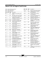
Страница 130: ...gin to blink 4 Continue to hold the run test toggle switch in the test position and count the blinks Note Before the fault codes are displayed the check engine light will blink a code 1 6 5 4 three times After the fault codes the check engine light will blink a code 1 6 5 4 three times again indicating the end of the stored codes Note If any fault codes are present the ECM will blink a three digit...

Страница 131: ...tage 217 ECT higher than expected 2 219 Max govern speed override 221 TPS1 higher than TPS2 222 TPS2 low voltage 223 TPS2 high voltage 236 TIP Active Code Description 237 TIP Low Voltage 238 TIP High Voltage 261 Injector Loop Open or Low side short to Ground 262 Injector Coil Shorted 264 Injector Loop Open or Low side short to Ground 265 Injector Coil Shorted 267 Injector Loop Open or Low side sho...

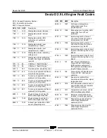
Страница 132: ... ground short 617 Start relay coil short to power 627 Fpump relay coil open 628 FPump motor loop open or high side shorted to ground 628 Fpump relay control ground short 629 FPump motor high side shorted to power 629 Fpump relay coil short to power Code Description 642 5VE1 low voltage 643 5VE1 high voltage 650 MIL open 652 5VE2 low voltage 653 5VE2 high voltage 685 Relay Coil Open 686 Relay Contr...

Страница 133: ... 1517 AUX analog PU3 high 1518 AUX analog PU3 low 1521 CHT higher than expected 1 1522 CHT higher than expected 2 1531 IVS Brake Trans Park interlock failure 1541 AUX analog PUD1 high 1542 AUX analog PUD1 low 1543 AUX analog PUD2 high 1544 AUX analog PUD2 low 1545 AUX analog PUD3 high Code Description 1551 AUX DIG1 high 1552 AUX DIG1 low 1553 AUX DIG2 high 1554 AUX DIG2 low 1555 AUX DIG3 high 1556...

Страница 134: ...S 2126 FPP1 higher than FPP2 2127 FPP2 low voltage 2128 FPP2 high voltage Code Description 2130 IVS stuck at idle FPP1 2 match 2131 IVS stuck off idle FPP1 2 match 2135 TPS1 2 simultaneous voltages out of range 2139 FPP1 lower than IVS limit 2140 FPP2 lower than IVS limit 2229 BP high pressure 2300 Primary Loop Open or Low side Short to Ground 2301 Primary Coil Shorted 2303 Primary Loop Open or Lo...

Страница 135: ...the safety rules and operating instructions in the appropriate operator s manual on your machine Be sure that all necessary tools and test equipment are available and ready for use About This Section There are two groups of schematics in this section Electrical Schematics Electrocution burn hazard Contact with electrically charged circuits could result in death or serious injury Remove all rings w...

Страница 136: ... terminal T circuits connect at terminal Circuits crossing no connection Quick disconnect terminal Circuit breaker with amperage Key switch Toggle Switch DPDT Toggle Switch SPDT Pump or Motor Tilt sensor Horn button normally open Emergency Stop button normally closed Resistor with ohm value Battery separator Gauge sending unit Oil temperature switch normally open Coolant temperature switch normall...

Страница 137: ...osition 3 way Differential sensing valve Filter with bypass relief valve Relief valve with pressure setting Priority flow regulator valve Solenoid operated proportional valve Directional valve mechanically activated Flow divider combiner valve Pilot operated 3 position 3 way shuttle valve Solenoid operated 2 position 3 way directional valve Counterbalance valve with pressure and pilot ratio Soleno...

Страница 138: ...S2 4 LS4 5 S8 6 LS3 Limit Switches and Sensors S24 LS1 LS5 LS2 LS4 S8 LS3 Platform overload sensor Limit switch boom fully retracted operational 40pin connector Limit switch boom fully retracted safety 2 pin connector Limit switch primary boom angle Limit switch secondary boom angle Turntable tilt sensor Limit switch turntable ...

Страница 139: ...ake circuit relay lift drive option CR30 Limit switch relay lift drive option CR76 Load sense aux recovery AS models CR51 Aircraft package option G Gauge G1 Battery Charge Indicator G2 Engine oil pressure G3 Engine coolant temp G4 Engine oil temp G6 Hour meter Item Description H Horn or Alarm H1 Tilt load sense alarm H4 Descent ground H6 Load sense ground JC Joystick JC1 Boom proportional joystick...

Страница 140: ... Fuel select switch ford efi only TS4 Hi low rpm switch TS6 Glow plug switch TS7 Platform rotate switch TS8 Jib rotate switch jib option TS9 Platform level switch TS13 Primary boom extend retract switch TS14 Drive speed switch TS15 Drive enable switch TS43 Heater switch option TS46 Proximity kill switch option TS47 Generator switch option TS51 Auxiliary pump toggle switch TS52 Engine start toggle ...

Страница 141: ...ector X101 ALC500 input out connectors X102 ALC500 input out connectors X103 ALC500 input out connectors X104 ALC500 input out connectors X105 ALC500 input out connectors X106 ALC500 input out connectors X107 ALC500 input out connectors X108 ALC500 input out connectors X109 ALC500 input out connectors X1 4 Circuit splice Wire Color Legend Item Description BL Blue BK Black BR Brown GN Green OR Oran...

Страница 142: ...y will sequence between engine hours and battery voltage every 5 seconds Active platform overload fault codes are also displayed 1 LCD display 2 red LED fault indicator 3 yellow LED battery indicator 4 green LED engine hours indicator 5 8 pin connector 8 Pin Connector Pin number Circuit Wire color 1 CAN High Yellow 2 CAN Low Green 3 12V B Heater Red 4 Not Used 5 12V B Red 6 Not Used 7 Not Used 8 G...

Страница 143: ...November 2020 Service and Repair Manual 131 Electrical Schematic Ford MSG425 ...

Страница 144: ...Service and Repair Manual November 2020 132 Z 45 XC Z 45 HF Part No 1268197GT Electrical Schematic Ford MSG425 ...

Страница 145: ...November 2020 Service and Repair Manual Part No 1268197GT Z 45 XC Z 45 HF 133 Electrical Schematic Deutz D2011 L03i and Perkins 404D 22 ...

Страница 146: ...Service and Repair Manual November 2020 134 Electrical Schematic Deutz D2011 L03i and Perkins 404D 22 ...

Страница 147: ...November 2020 Service and Repair Manual 135 Electrical Schematic Deutz D 2 9 L4 ...

Страница 148: ...Service and Repair Manual November 2020 136 Z 45 XC Z 45 HF Part No 1268197GT Electrical Schematic Deutz D 2 9 L4 ...

Страница 149: ...November 2020 Service and Repair Manual Part No 1268197GT Z 45 XC Z 45 HF 137 Engine Wire Harness Deutz D 2 9 L4 ...

Страница 150: ...Service and Repair Manual November 2020 138 Engine Wire Harness Deutz D 2 9 L4 ...

Страница 151: ...November 2020 Service and Repair Manual 139 Electrical Schematic Deutz TD 2 2 L3 ...

Страница 152: ...Service and Repair Manual November 2020 140 Z 45 XC Z 45 HF Part No 1268197GT Electrical Schematic Deutz TD 2 2 L3 ...

Страница 153: ...November 2020 Service and Repair Manual Part No 1268197GT Z 45 XC Z 45 HF 141 Engine Wire Harness Deutz TD 2 2 L3 Page 1 ...

Страница 154: ...Service and Repair Manual November 2020 142 Engine Wire Harness Deutz TD 2 2 L3 Page 1 ...

Страница 155: ...November 2020 Service and Repair Manual Part No 1268197GT Z 45 XC Z 45 HF 143 Engine Wire Harness Deutz TD 2 2 L3 Page 2 ...

Страница 156: ...Service and Repair Manual November 2020 144 Engine Wire Harness Deutz TD 2 2 L3 Page 2 ...

Страница 157: ...November 2020 Service and Repair Manual 145 Electrical Schematic Perkins 404F E22T ...

Страница 158: ...Service and Repair Manual November 2020 146 Z 45 XC Z 45 HF Part No 1268197GT Electrical Schematic Perkins 404F E22T ...

Страница 159: ...November 2020 Service and Repair Manual Part No 1268197GT Z 45 XC Z 45 HF 147 Engine Wire Harness Perkins 404F E22T ...

Страница 160: ...Service and Repair Manual November 2020 148 Engine Wire Harness Perkins 404F E22T ...

Страница 161: ...November 2020 Service and Repair Manual 149 Electrical Schematic Function Controls ANSI CSA ...

Страница 162: ...Service and Repair Manual November 2020 150 Z 45 XC Z 45 HF Part No 1268197GT Electrical Schematic Function Controls ANSI CSA ...

Страница 163: ...November 2020 Service and Repair Manual Part No 1268197GT Z 45 XC Z 45 HF 151 Electrical Schematic Function Controls CE ...

Страница 164: ...Service and Repair Manual November 2020 152 Electrical Schematic Function Controls CE ...

Страница 165: ...November 2020 Service and Repair Manual 153 Electrical Schematic Platform Overload ...

Страница 166: ...Service and Repair Manual November 2020 154 Z 45 XC Z 45 HF Part No 1268197GT Electrical Schematic Platform Overload ...

Страница 167: ...November 2020 Service and Repair Manual Part No 1268197GT Z 45 XC Z 45 HF 155 Electrical Schematic Options Wiring Diagram ...

Страница 168: ...Service and Repair Manual November 2020 156 Electrical Schematic Options Wiring Diagram ...

Страница 169: ...November 2020 Service and Repair Manual 157 Ground Control Box Switch Panel Wiring Diagram Deutz D2011L03i and Perkins 404D ANSI CSA ...

Страница 170: ...Service and Repair Manual November 2020 158 Z 45 XC Z 45 HF Part No 1268197GT Ground Control Box Switch Panel Wiring Diagram Deutz D2011L03i and Perkins 404D ANSI CSA ...

Страница 171: ...November 2020 Service and Repair Manual Part No 1268197GT Z 45 XC Z 45 HF 159 Ground Control Box Terminal Strip Wiring Diagram Deutz D2011L03i and Perkins 404D 22 ANSI CSA ...

Страница 172: ...Service and Repair Manual November 2020 160 Ground Control Box Terminal Strip Wiring Diagram Deutz D2011L03i and Perkins 404D 22 ANSI CSA ...

Страница 173: ...November 2020 Service and Repair Manual 161 Ground Control Box Switch Panel Wiring Diagram Deutz D 2 9 L4 and Perkins 404F E22T ANSI CSA ...

Страница 174: ...Service and Repair Manual November 2020 162 Z 45 XC Z 45 HF Part No 1268197GT Ground Control Box Switch Panel Wiring Diagram Deutz D 2 9 L4 and Perkins 404F E22T ANSI CSA ...

Страница 175: ...November 2020 Service and Repair Manual Part No 1268197GT Z 45 XC Z 45 HF 163 Ground Control Box Terminal Strip Wiring Diagram Deutz D 2 9 L4 and Perkins 404F E22T ANSI CSA ...

Страница 176: ...Service and Repair Manual November 2020 164 Ground Control Box Terminal Strip Wiring Diagram Deutz D 2 9 L4 and Perkins 404F E22T ANSI CSA ...

Страница 177: ...November 2020 Service and Repair Manual 165 Ground Control Box Switch Panel Wiring Diagram Ford MSG425 ANSI CSA ...

Страница 178: ...Service and Repair Manual November 2020 166 Z 45 XC Z 45 HF Part No 1268197GT Ground Control Box Switch Panel Wiring Diagram Ford MSG425 ANSI CSA ...

Страница 179: ...November 2020 Service and Repair Manual Part No 1268197GT Z 45 XC Z 45 HF 167 Ground Control Box Terminal Strip Wiring Diagram Ford MSG425 ANSI CSA ...

Страница 180: ...Service and Repair Manual November 2020 168 Ground Control Box Terminal Strip Wiring Diagram Ford MSG425 ANSI CSA ...

Страница 181: ...November 2020 Service and Repair Manual 169 Ground Control Box Switch Panel Wiring Diagram CE ...

Страница 182: ...Service and Repair Manual November 2020 170 Z 45 XC Z 45 HF Part No 1268197GT Ground Control Box Switch Panel Wiring Diagram CE ...

Страница 183: ...November 2020 Service and Repair Manual Part No 1268197GT Z 45 XC Z 45 HF 171 Ground Control Box Terminal Strip Wiring Diagram CE ...

Страница 184: ...Service and Repair Manual November 2020 172 Ground Control Box Terminal Strip Wiring Diagram CE ...

Страница 185: ...November 2020 Service and Repair Manual 173 Platform Control Box Switch Panel Wiring Diagram ...

Страница 186: ...Service and Repair Manual November 2020 174 Z 45 XC Z 45 HF Part No 1268197GT Platform Control Box Switch Panel Wiring Diagram ...

Страница 187: ...November 2020 Service and Repair Manual Part No 1268197GT Z 45 XC Z 45 HF 175 Platform Control Box Terminal Strip Wiring Diagram ...

Страница 188: ...Service and Repair Manual November 2020 176 Platform Control Box Terminal Strip Wiring Diagram ...

Страница 189: ...November 2020 Service and Repair Manual 177 Platform Control Box Relay Wiring Diagram ANSI CSA ...

Страница 190: ...Service and Repair Manual November 2020 178 Z 45 XC Z 45 HF Part No 1268197GT Platform Control Box Relay Wiring Diagram ANSI CSA ...

Страница 191: ...November 2020 Service and Repair Manual Part No 1268197GT Z 45 XC Z 45 HF 179 Platform Control Box Relay Wiring Diagram CE ...

Страница 192: ...Service and Repair Manual November 2020 180 Platform Control Box Relay Wiring Diagram CE ...

Страница 193: ...November 2020 Service and Repair Manual 181 Hydraulic Schematic CE to Z4525XCM 1500 ...

Страница 194: ...Service and Repair Manual November 2020 182 Z 45 XC Z 45 HF Part No 1268197GT Hydraulic Schematic CE to Z4525XCM 1500 ...

Страница 195: ...November 2020 Service and Repair Manual Part No 1268197GT Z 45 XC Z 45 HF 183 Hydraulic Schematic ANSI CSA CE from Z4525XCF 101 Z4525XCM 1501 ...

Страница 196: ...Service and Repair Manual November 2020 184 Hydraulic Schematic ANSI CSA CE from Z4525XCF 101 Z4525XCM 1501 Z 45 XC Z 45 HF Part No 1268197GT Ser vice and R epair M anual November 2020 ...

Страница 197: ......

Отзывы: