Service and Repair Manual
October 2021
Platform Components
18
Z
®
-34/22 Bi-Energy
Part No. 1268515GT
2-1
Platform Leveling Slave Cylinder
The slave cylinder and the rotator pivot are the two
primary supports for the platform. The slave
cylinder keeps the platform level through the entire
range of boom motion. It operates in a closed-
circuit hydraulic loop with the master cylinder. The
slave cylinder is equipped with counterbalance
valves to prevent movement in the event of a
hydraulic line failure.
How to Re mov e th e Platfo rm Leveli ng Slave Cylind er
How to Remove the Platform
Leveling Slave Cylinder
Note: Before cylinder removal is considered, bleed
the slave cylinder to be sure there is no air in the
closed loop.
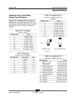
Note: When removing a hose assembly or fitting,
the O-ring (if equipped) on the fitting and/or hose
end must be replaced. All connections must be
torqued to specification during installation. Refer to
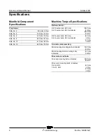
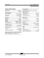
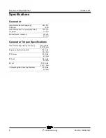
Specifications,
Hydraulic Hose and Fitting Torque
Specifications.
1 Extend the boom until the slave cylinder
barrel-end pivot pin is accessible.
2 Raise the boom slightly and place blocks
under the platform for support. Lower the
boom until the platform is resting on the
blocks.
3 Remove the pin retainer fastener from the
rod-end pivot pin.
4 Remove the external snap ring from the
barrel-end pivot pin.
5 Use a soft metal drift to remove the rod-end
pivot pin.
6 Use a soft metal drift to remove the barrel-end
pivot pin.
7 Carefully pull the cylinder out of the boom.
8 Tag and disconnect the hydraulic hoses from
the slave cylinder and connect them
togetherwith a connector. Cap the fittings on
the cylinder.
Bodily injury hazard. Spraying
hydraulic oil can penetrate and
burn skin. Loosen hydraulic
connections very slowly to allow
the oil pressure to dissipate
gradually. Do not allow oil to
squirt or spray.
How to Blee d th e L eveling Slave Cylin der
How to Bleed the Slave Cylinder
1 Raise the jib boom to a horizontal position.
2 Move the platform level toggle switch up and
down through two platform leveling cycles to
remove any air that might be in the system.
Содержание Genie Z-34/22
Страница 63: ...October 2021 Service and Repair Manual Manifolds Part No 1268515GT Z 34 22 Bi Energy 51 ...
Страница 85: ...October 2021 Service and Repair Manual 73 Electrical Schematic ANSI CSA from SN Z3414 9686 to Z34F 12065 ...
Страница 88: ...Service and Repair Manual October 2021 76 Electrical Schematic ANSI CSA from SN Z3414 9686 to Z34F 12065 ...
Страница 89: ...October 2021 Service and Repair Manual 77 Electrical Schematic ANSI CSA from SN Z34F 12066 ...
Страница 92: ...Service and Repair Manual October 2021 80 Electrical Schematic ANSI CSA from SN Z34F 12066 ...
Страница 93: ...October 2021 Service and Repair Manual 81 GBOX Switch Panel Wiring Diagram ANSI CSA from SN Z3414 9686 ...
Страница 96: ...Service and Repair Manual October 2021 84 GBOX Terminal Strip Wiring Diagram ANSI CSA from SN Z3414 9686 ...
Страница 97: ...October 2021 Service and Repair Manual 85 PBOX Wiring Diagram ANSI CSA from SN Z3414 9686 ...
Страница 99: ...October 2021 Service and Repair Manual 87 Electrical Schematic CE AS from SN Z3414 9686 to Z34F 12065 ...
Страница 102: ...Service and Repair Manual October 2021 90 Electrical Schematic CE AS from SN Z3414 9686 to Z34F 12065 ...
Страница 103: ...October 2021 Service and Repair Manual 91 Electrical Schematic CE AS from SN Z34F 12066 ...
Страница 106: ...Service and Repair Manual October 2021 94 Electrical Schematic CE AS from SN Z34F 12066 ...
Страница 107: ...October 2021 Service and Repair Manual 95 GBOX Switch Panel Wiring Diagram CE AS from SN Z3414 9686 ...
Страница 110: ...Service and Repair Manual October 2021 98 GBOX Terminal Strip Wiring Diagram CE AS from SN Z3414 9686 ...
Страница 111: ...October 2021 Service and Repair Manual 99 Platform Control Box Wiring Diagram CE AS from SN Z3414 9686 ...
Страница 114: ...Service and Repair Manual October 2021 102 Power Cable Wiring Diagram from SN Z3414 9686 ...
Страница 115: ...October 2021 Service and Repair Manual 103 Drive Contactor Panel Wiring Diagram ...
Страница 116: ...Service and Repair Manual October 2021 104 Z 34 22 Bi Energy Part No 1268515GT Drive Contactor Panel Wiring Diagram ...
Страница 117: ...October 2021 Service and Repair Manual Part No 1268515GT Z 34 22 Bi Energy 105 Manifold and Limit Switch Wiring Diagram ...
Страница 118: ...Service and Repair Manual October 2021 106 Manifold and Limit Switch Wiring Diagram ...
Страница 119: ...October 2021 Service and Repair Manual 107 LVI BCI Option Wiring Diagram ...
Страница 120: ...Service and Repair Manual October 2021 108 Z 34 22 Bi Energy Part No 1268515GT LVI BCI Option Wiring Diagram ...
Страница 121: ...October 2021 Service and Repair Manual Part No 1268515GT Z 34 22 Bi Energy 109 Charger Interlock Option ...
Страница 122: ...Service and Repair Manual October 2021 110 Charger Interlock Option ...
Страница 123: ...October 2021 Service and Repair Manual 111 Engine Wiring Diagram ...
Страница 124: ...Service and Repair Manual October 2021 112 Z 34 22 Bi Energy Part No 1268515GT Engine Wiring Diagram ...
Страница 126: ...Service and Repair Manual October 2021 114 Contact Alarm Option from SN Z34F 12066 ...
Страница 127: ...October 2021 Service and Repair Manual 115 Fuel Level Sensor Option from SN Z34F 12066 ...
Страница 129: ...October 2021 Service and Repair Manual 117 Hydraulic Schematic ...
Страница 131: ......


