Service and Repair Manual
June 2021
Scissor Components
24
GS
™
-84 • GS
™
-90
Part No. 1306587GT
10 Place a rod through the cable tray pivot pin
and twist to remove the pin. Lower the cable
tray down.
Component damage hazard.
Cables can be damaged if they
are kinked or pinched.
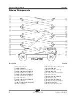
11 Secure both ends of the number 3 inner and
outer arms (index #2 and #11) together with a
strap or other suitable device.
12 Attach a lifting strap from an overhead crane
to the number 3 inner and outer arms (index
#2 and #11) at the steer end of the machine.
Do not apply any lifting pressure.
13 Attach a lifting strap from an overhead crane
to the number 3 inner and outer arms (index
#2 and #11) at the non-steer end of the
machine. Do not apply any lifting pressure.
14 Remove the pin retaining fasteners from both
number 3 pivot pins (index #4) at the non-
steer end of the machine. Do not remove the
pins.
15 Remove the pin retaining fasteners from both
number 3 pivot pins (index #13) at the steer
end of the machine. Do not remove the pins.
16 Use a slide hammer to remove both number
3 pivot pins (index #4) from the non-steer end
of the machine.
17 Use a slide hammer to remove both number
3 pivot pins (index #13) from the steer end of
the machine.
18 Carefully remove the number 3 inner and
outer arms (index #2 and #11) from the
machine.
Crushing hazard. The number
3 inner and outer arms could
become unbalanced and fall
when they are removed from the
machine if not properly
supported by the overhead
crane.
Note: If further disassembly of the scissor arm pair
is required, refer to Repair Procedure,
How to
Disassemble a Scissor Arm Pair.
19 Secure the non-steer end of the number
2 inner and outer arms (index #5 and #6) and
the non-steer end of the number 1 inner and
outer arms (index #8 and #16) together with a
strap or other suitable device.
20 Attach a lifting strap from an overhead crane
to the number 1 outer arm (index #16) at the
non-steer end of the machine. Do not apply
any lifting pressure.
21 Remove the pin retaining fasteners from the
number 1 pivot pins (index #10) at the non-
steer end of the machine.
22 Use a slide hammer to remove both number
1 pivot pins (index #10) from the non-steer
end of the machine.
23 Carefully lift the number 1 outer arm at the
non-steer end approximately 15 inches /
40 cm.
24 Place a 6 x 6 x 32 inch / 15 x 15 x 80 cm long
block across both sides of the chassis under
the barrel end of the lift cylinder.
Содержание Genie GS-3384
Страница 93: ...June 2021 Service and Repair Manual Part No 1306587GT GS 84 GS 90 79 This page intentionally left blank...
Страница 181: ...June 2021 Service and Repair Manual Wiring Diagram Platform Control Box Part No 1306587GT GS 84 GS 90 167...
Страница 183: ...June 2021 Service and Repair Manual Wiring Diagram 12 kW Hydraulic Generator option Part No 1306587GT GS 84 GS 90 169...
Страница 185: ...June 2021 Service and Repair Manual 171 Ford MSG 425 Engine Wire Harness...
Страница 186: ...Service and Repair Manual June 2021 172 GS 84 GS 90 Part No 1306587GT Ford MSG 425 EFI Engine Wire Harness...
Страница 187: ...June 2021 Service and Repair Manual Part No 1306587GT GS 84 GS 90 173 Deutz D 2 9 L4 Engine Wire Harness...
Страница 188: ...Service and Repair Manual June 2021 174 Deutz D 2 9 L4 Engine Wire Harness...
Страница 189: ...June 2021 Service and Repair Manual 175 Deutz TD 2 2 L3 Engine Wire Harness...
Страница 190: ...Service and Repair Manual June 2021 176 GS 84 GS 90 Part No 1306587GT Deutz TD 2 2 L3 Engine Wire Harness...
Страница 191: ...June 2021 Service and Repair Manual Part No 1306587GT GS 84 GS 90 177 Deutz TD 2 2 L3 Engine Wire Harness...
Страница 192: ...Service and Repair Manual June 2021 178 Deutz TD 2 2 L3 Engine Wire Harness...
Страница 193: ...June 2021 Service and Repair Manual 179 Hydraulic Schematic...
Страница 194: ...Service and Repair Manual June 2021 180 GS 84 GS 90 Part No 1306587GT Hydraulic Schematic...
Страница 195: ...June 2021 Service and Repair Manual Part No 1306587GT GS 84 GS 90 181 Hydraulic Schematic...
Страница 196: ...Service and Repair Manual June 2021 182 Hydraulic Schematic...
Страница 197: ...June 2021 Service and Repair Manual 183 Electrical Schematic Ford Engine Models ANSI CSA...
Страница 198: ...Service and Repair Manual June 2021 184 GS 84 GS 90 Part No 1306587GT Electrical Schematic Ford Engine Models ANSI CSA...
Страница 199: ...June 2021 Service and Repair Manual Part No 1306587GT GS 84 GS 90 185 Electrical Schematic Ford Engine Models ANSI CSA...
Страница 200: ...Service and Repair Manual June 2021 186 Electrical Schematic Ford Engine Models ANSI CSA...
Страница 201: ...June 2021 Service and Repair Manual 187 Electrical Schematic Deutz Engine Models ANSI CSA...
Страница 202: ...Service and Repair Manual June 2021 188 GS 84 GS 90 Part No 1306587GT Electrical Schematic Deutz Engine Models ANSI CSA...
Страница 203: ...June 2021 Service and Repair Manual Part No 1306587GT GS 84 GS 90 189 Electrical Schematic Deutz Engine Models ANSI CSA...
Страница 204: ...Service and Repair Manual June 2021 190 Electrical Schematic Deutz Engine Models ANSI CSA...
Страница 205: ...June 2021 Service and Repair Manual Part No 1306587GT GS 84 GS 90 191 Electrical Schematic SCON ANSI CSA...
Страница 206: ...Service and Repair Manual June 2021 192 Electrical Schematic SCON ANSI CSA...
Страница 207: ...June 2021 Service and Repair Manual 193 Electrical Schematic Ford Engine Models AS CE...
Страница 208: ...Service and Repair Manual June 2021 194 GS 84 GS 90 Part No 1306587GT Electrical Schematic Ford Engine Models AS CE...
Страница 209: ...June 2021 Service and Repair Manual Part No 1306587GT GS 84 GS 90 195 Electrical Schematic Ford Engine Models AS CE...
Страница 210: ...Service and Repair Manual June 2021 196 Electrical Schematic Ford Engine Models AS CE...
Страница 211: ...June 2021 Service and Repair Manual 197 Electrical Schematic Deutz Engine Models AS CE...
Страница 212: ...Service and Repair Manual June 2021 198 GS 84 GS 90 Part No 1306587GT Electrical Schematic Deutz Engine Models AS CE...
Страница 213: ...June 2021 Service and Repair Manual Part No 1306587GT GS 84 GS 90 199 Electrical Schematic Deutz Engine Models AS CE...
Страница 214: ...Service and Repair Manual June 2021 200 Electrical Schematic Deutz Engine Models AS CE...
Страница 215: ...June 2021 Service and Repair Manual Part No 1306587GT GS 84 GS 90 201 Electrical Schematic SCON AS CE...
Страница 217: ......

