background image

June 2021


Service and Repair Manual


Manifolds


Part No. 1306587GT


GS

-84 • GS

-90


91 


7-7 

Valve Adjustments - Traction 

Manifold 

How to Adjust the Charge Pressure Relief Valve 

How to Adjust the Charge 

Pressure Relief Valve 

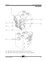
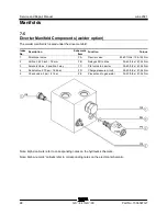
Note: Refer to Drive Manifold Component list to 

locate the charge pressure relief valve. 
1  Connect a 0 to 600 psi / 0 to 50 bar pressure 

gauge to test port #2 on the drive manifold. 

2  Start the engine from the platform controls. 
3  Drive the machine slowly in the direction 

indicated by the blue arrow on the platform 

controls and observe the pressure reading on 

the pressure gauge. Refer to Specifications, 

Hydraulic Components Specifications. 


Component damage hazard. 

Driving the machine in reverse 

will place excessive pressure on 

the pressure gauge and will 

damage the gauge. Do not drive 

the machine in a reverse 

direction. 

4  Turn the engine off. Use a wrench to hold the 

charge pressure relief valve and remove the 

cap (item EE). 

5  Adjust the internal hex socket. Turn it 

clockwise to increase the pressure or 

counterclockwise to decrease the pressure. 

Install the relief valve cap. 

6  Repeat steps 2 through 3 to confirm the relief 

valve pressure. 


Содержание Genie GS-3384

Страница 1: ...401 This manual includes Repair procedures Fault Codes Electrical and Hydraulic Schematics GS 3390 from GS90F 56000 from GS90D 3201 GS 4390 GS 5390 For detailed maintenance procedures refer to the ap...

Страница 2: ...ife Unrestricted with proper operation inspection and scheduled maintenance Technical Publications Genie has endeavored to deliver the highest degree of accuracy possible However continuous improvemen...

Страница 3: ...on Date Section Procedure Page Description A 4 2021 Initial Release A1 6 2021 Repair 9 1 Reference Examples Electronic Version Click on any content or procedure in the Table of Contents to view the up...

Страница 4: ...and Repair Manual June 2021 Introduction iv GS 84 GS 90 Part No 1306587GT Serial Number Legend 1 Model 2 Facility code 3 Sequence number 4 Serial label located inside cover 5 Serial number stamped on...

Страница 5: ...Many of the hazards identified in the operator s manual are also safety hazards when maintenance and repair procedures are performed Do Not Perform Maintenance Unless You are trained and qualified to...

Страница 6: ...ushing hazards such as moving parts free swinging or unsecured components when lifting or placing loads Always wear approved steel toed shoes Workplace Safety Any person working on or around a machine...

Страница 7: ...on 2 Specifications 1 Machine Specifications 1 Performance Specifications 2 Hydraulic Oil Specifications 3 Hydraulic Component Specifications 6 Manifold Component Specifications 7 Ford MSG 425 EFI Eng...

Страница 8: ...to Disassemble the Scissor Assembly 23 How to Disassemble a Scissor Arm Pair 27 3 2 Scissor Assembly GS 4390 29 How to Disassemble the Scissor Assembly 29 How to Disassemble a Scissor Arm Pair 33 3 3...

Страница 9: ...ontrols 56 5 1 Auxiliary Platform Lowering 56 5 2 Controller Adjustments 56 How to Determine the Revision Level 57 How to Adjust the Stowed Drive Speed 57 How to Adjust the High Torque Drive Speed 58...

Страница 10: ...on Manifold Components 84 7 4 Oscillate Manifold Components GS 90 option 86 7 5 Welder Manifold Components option 88 7 6 Valve Adjustments Function Manifold 89 How to Adjust the System Relief Valve 89...

Страница 11: ...tor and Brake 104 How to Remove a Drive Motor and Brake 104 10 2 Drive Hub 105 How to Remove a Drive Hub 105 10 3 Oscillating Axle 106 Outrigger Components 107 11 1 Outrigger Cylinder 107 How to Remov...

Страница 12: ...L3 Models 124 Fault Code Display Flashing and Solid LED s Deutz D 2 9 L4 Models 125 Soft Key Functions and Icons Deutz D 2 9 L4 Models 126 Soft Key Functions and Icons Deutz TD 2 2 L3 Models 127 Main...

Страница 13: ...ine Relay Layout 162 Electronic Control Module Layout 163 Electronic Control Module Pin Out Legend 164 Ground Controls Wiring Panel Layout 166 Wiring Diagram Platform Control Box 167 Limit Switch Lege...

Страница 14: ...CSA Models 183 Electrical Schematic Ford Engine Models ANSI CSA 184 Electrical Schematic Deutz Engine Models ANSI CSA 188 Electrical Schematic SCON ANSI CSA 191 Electrical Schematics AS and CE Models...

Страница 15: ...foam filled all models Tire size 33 16LL500 Tire ply rating 10 Tire diameter x Tire width 33 in x 16 in 83 8 cm x 41 cm Wheel diameter x width 19 5 in x 14 in 49 5 cm x 35 6 cm Weight foam filled 419...

Страница 16: ...tform stowed 4 mph 40 ft 6 8 sec 6 4 km h 12 2 m 6 8 sec Platform raised 0 7 mph 40 ft 39 sec 1 1 km h 12 2 m 39 sec Braking distance maximum High range on paved surface 60 in 152 4 cm Gradeability Se...

Страница 17: ...HP 5046 Note Genie specifications require additional equipment and special installation instructions for the approved optional fluids Consult Genie Product Support before use Optional fluids may not...

Страница 18: ...0 F 18 C Note Do not operate the machine when the ambient temperature is below 20 F 29 C with Rando HD Premium MV Chevron 5606A Hydraulic Oil Fluid Properties ISO Grade 15 Viscosity index 300 Kinemat...

Страница 19: ...Tellus S4 VX Fluid Properties ISO Grade 32 Viscosity index 300 Kinematic Viscosity cSt 200 F 100 C cSt 104 F 40 C 9 33 8 Brookfield Viscosity cSt 4 F 20 C cSt 13 F 25 C cSt 40 F 40 C 481 702 4 2624 Fl...

Страница 20: ...iliary power unit Relief valve 3700 psi 255 bar Function manifold System relief valve pressure maximum GS 3384 and GS 3390 2700 to 2900 psi 186 to 200 bar System relief valve pressure maximum GS 4390...

Страница 21: ...gulator 1 gpm 3 8 L min Generator manifold option Relief valve 2400 psi 165 5 bar Flow rate maximum 4 3 gpm 16 3 L min Welder manifold option Relief valve 270 psi 18 6 bar Hydraulic motor welder optio...

Страница 22: ...o 0 62 bar Oil viscosity requirements Extreme operating temperatures may require the use of alternative engine oils For oil requirements refer to the Engine Operator Handbook on your machine Electroni...

Страница 23: ...ar Fuel requirement For fuel requirements refer to the engine Operator Manual for your engine Lubrication system Oil pressure 20 to 44 psi 1 4 to 3 bar Oil capacity including filter 9 5 quarts 9 liter...

Страница 24: ...with 15W 40 Extreme operating temperatures may require the use of alternative engine oils For oil requirements refer to the Engine Operator Manual for your engine Oil temperature switch Installation t...

Страница 25: ...liters Oil viscosity requirements Low ash oil required 22 F to 86 F 30 C to 30 C 5W 30 synthetic 4 F to 90 F 20 C to 32 C 10W 40 Above 23 F 5 C 20W 50 Unit ships with 15W 40 Extreme operating tempera...

Страница 26: ...ne continued Starter motor Current draw normal load 250A to 400A Brush length new 0 72 in 18 5 mm Brush length minimum 0 27 in 7 mm Battery Type 12V DC Quantity 1 Cold cranking ampere 1000A Reserve ca...

Страница 27: ...4 16 1 1 2 10 7 8 14 1 1 2 12 1 1 16 12 1 1 4 16 1 5 16 12 1 20 1 5 8 12 1 24 1 7 8 12 1 SAE O ring Boss Port tube fitting installed into Aluminum all types SAE Dash Size Torque 4 14 ft lbs 19 Nm 6 23...

Страница 28: ...and retained properly 4 Position the tube and nut squarely on the face seal end of the fitting and tighten the nut finger tight 5 Tighten the nut or fitting to the appropriate torque Refer to the appr...

Страница 29: ...number of flats for the proper tightening position Note The marks indicate the correct tightening positions have been determined Use the second mark on the body hex fitting to properly tighten the joi...

Страница 30: ...te operator s manual on your machine Be sure that all necessary tools and parts are available and ready for use Use only Genie approved replacement parts Read each procedure completely and adhere to t...

Страница 31: ...t personnel to potential personal injury hazards Obey all safety messages that follow this symbol to avoid possible injury or death Indicates a imminently hazardous situation which if not avoided will...

Страница 32: ...Push in the red Emergency Stop button to the off position at both the ground and platform controls 2 Loosen the platform control box lid retaining fasteners Open the control box lid 3 Visually locate...

Страница 33: ...m makes contact with the cross tube 4 Cut the zip ties that secure the power to platform wiring to the bottom of the platform Component damage hazard Be sure not to cut the power to platform wiring 5...

Страница 34: ...rap from a second overhead crane under the platform at the non steer end of the machine for support Do not apply any lifting pressure Component damage hazard The platform railings can be damaged if us...

Страница 35: ...tform V roller wheels 4 At the platform extension deck to be removed position a fork lift with the forks even with the bottom of the platform extension deck 5 Lift the platform extension deck lock han...

Страница 36: ...umber 2 outer arm 6 Number 2 inner arm 7 Number 2 pivot pin non steer end 8 Number 1 inner arm 9 Lift cylinder barrel end pivot pin 10Number 1 pivot pins non steer end 11Number 3 outer arm 12Lift cyli...

Страница 37: ...lift cylinder rod end pivot pin index 12 Do not remove the pin 4 Attach a lifting strap from an overhead crane to the lifting eye at the rod end of the lift cylinder 5 Use a soft metal drift to remove...

Страница 38: ...machine 17 Use a slide hammer to remove both number 3 pivot pins index 13 from the steer end of the machine 18 Carefully remove the number 3 inner and outer arms index 2 and 11 from the machine Crush...

Страница 39: ...teners from the cable tray pivot pin at the cross tube of the number 2 inner arm index 6 36 Place a rod through the cable tray pivot pin and twist to remove the pin Lower the cable tray onto the numbe...

Страница 40: ...mber 1 inner and outer arms index 8 and 16 at the non steer end of the machine Do not apply any lifting pressure 49 Remove the pin retaining fasteners from both chassis centering link pivot pins index...

Страница 41: ...strap to the end of the scissor arm that has the casting pointing upwards 1 outer arm 2 inner arm 2 Attach a lifting strap from a second overhead crane to the end of the inner arm Note Attach the lif...

Страница 42: ...center pivot pin Qty 2 8 Number 2 inner arm 9 Number 2 pivot pin non steer end 10Number 1 inner arm 11Lower lift cylinder barrel end pivot pin 12Number 1 outer arm 13Number 1 pivot pins non steer end...

Страница 43: ...Attach a lifting strap from an overhead crane to the number 4 inner and outer arms index 14 and 2 at the steer end of the machine Do not apply any lifting pressure 6 Attach a lifting strap from an ov...

Страница 44: ...r spray 20 Cut the zip ties attaching the hydraulic hoses to the lift cylinder Lay the hoses out of the way Component damage hazard Hoses can be damaged if they are kinked or pinched 21 Remove the cab...

Страница 45: ...ng pressure 34 Remove the pin retaining fasteners from the number 1 pivot pins index 13 at the non steer end of the machine 35 Use a slide hammer to remove both number 1 pivot pins index 13 from the n...

Страница 46: ...apply any lifting pressure 53 Remove the pin retaining fasteners from both number 2 pivot pins index 9 at the non steer end of the machine Do not remove the pins 54 Remove the pin retaining fasteners...

Страница 47: ...chine Crushing hazard The number 1 inner and outer arms could become unbalanced and fall when they are removed from the machine if not properly supported by the overhead crane Note If further disassem...

Страница 48: ...of the scissor arm pair Lower the scissor arm pair onto the block 5 Remove the external snap rings from both center pivot pins 6 Use a soft metal drift to remove both center pins 7 Carefully separate...

Страница 49: ...umber 3 center pivot pin Qty 2 12Number 2 center pivot pin Qty 2 13Number 2 pivot pin non steer end 14Number 1 inner arm 15Lower lift cylinder barrel end pivot pin 16Number 1 outer arm 17Number 1 pivo...

Страница 50: ...ice 5 Attach a lifting strap from an overhead crane to the number 5 inner and outer arms index 2 and 18 at the steer end of the machine Do not apply any lifting pressure 6 Attach a lifting strap from...

Страница 51: ...ve both number 4 pivot pins index 7 from the non steer end of the machine 22 Use a slide hammer to remove both number 4 pivot pins index 22 from the steer end of the machine 23 Support the rod end of...

Страница 52: ...dex 8 and 23 together with a strap or other suitable device 37 Attach a lifting strap from an overhead crane to the number 3 inner and outer arms index 8 and 23 at the steer end of the machine Do not...

Страница 53: ...ber 1 outer arm index 16 onto the block Crushing hazard Keep hands clear of moving parts when lowering the arms onto the block 51 Attach a lifting strap from an overhead crane to the lifting eyes on t...

Страница 54: ...er end of the machine Do not remove the pins 67 Use a slide hammer to remove both number 2 pivot pins index 13 from the non steer end of the machine 68 Use a slide hammer to remove both number 2 pivot...

Страница 55: ...supported by the overhead crane Note If further disassembly of the scissor arm pair is required refer to Repair Procedure How to Disassemble a Scissor Arm Pair How to Disassemble a Scissor Arm Pair Ho...

Страница 56: ...m Wear Pad 1 Place a lifting strap from an overhead crane under the platform at the steer end of the machine for support Do not attach the lifting straps from the overhead crane to the platform railin...

Страница 57: ...s and the pin retaining fasteners How to Replace the Chassis Scissor Arm Wear Pads How to Replace the Chassis Scissor Arm Wear Pads Note If removing the steer end slide blocks the engine top and side...

Страница 58: ...ff the slide block pivot pins 14 Remove the pin retaining fasteners from the chassis slide block pivot pin 15 Use a slide hammer to remove the chassis slide block pivot pin Remove the slide block from...

Страница 59: ...f equipped on the fitting and or hose end must be replaced All connections must be torqued to specification during installation Refer to Specifications Hydraulic Hose and Fitting Torque Specifications...

Страница 60: ...the pin Crushing hazard The lift cylinder will fall unless it is properly supported 10 Carefully lower the cylinder onto the cross tube of the number 2 inner arm Protect the cylinder rod from damage...

Страница 61: ...e the platform approximately 18 feet 5 5 m from the ground 2 Release the safety arm latch lift the safety arm and rotate to a vertical position Lock the safety arm in position Note Be sure that the sa...

Страница 62: ...t is properly supported 10 Carefully lower the cylinder to a horizontal position Protect the cylinder rod from damage Component damage hazard The counterbalance valve on the lift cylinder can be damag...

Страница 63: ...he platform after the safety arm makes contact with the cross tube 4 Disconnect the height angle sensor from the main harness 5 Remove the retaining fasteners securing the angle sensor mount to the se...

Страница 64: ...Flex Plate The flex plate acts as a coupler between the engine and the pump It is bolted to the engine flywheel and has a splined center to drive the pump 1 pump 2 pump shaft 3 coupler 4 flex plate 5...

Страница 65: ...rs 13 Carefully pull the pump and bell housing away from the engine and secure it from moving Component damage hazard Hoses can be damaged if they are kinked or pinched 14 Remove the flex plate mounti...

Страница 66: ...40 ft lbs 54 Nm Flex plate bolt torque sequence 4 Install the pump coupler onto the pump shaft with the set screw toward the pump Leave the appropriate gap between coupler and pump end plate for your...

Страница 67: ...MSG 425 Models How to Retrieve Engine Fault Codes The ECM constantly monitors the engine by the use of sensors on the engine The ECM also uses signals from the sensors to initiate sequential fuel inje...

Страница 68: ...e Engine Fault Codes for your specific engine model Use the Fault Code Chart to aid in identifying the fault 4 5 Engine Fault Codes Deutz D 2 9 L4 Models How to Retrieve Engine Fault Codes The ECM con...

Страница 69: ...ctions Standstill regeneration If passive regeneration does not attain an adequate reduction of the soot contamination the particle filter will continue to become contaminated with soot and a standsti...

Страница 70: ...eds are determined by the percentage of total ECM voltage output The speeds of the following machine functions may be adjusted to compensate for wear in the hydraulic pump and drive motors Stowed driv...

Страница 71: ...latform down buttons Pull out the red Emergency Stop button to the on position at the ground controls Result TUNE SPEEDS is showing in the diagnostic display window The ECM is now in programming mode...

Страница 72: ...ulting in death or serious injury Note On machines with software revision B1 or lower high torque drive speeds in forward and reverse are simultaneously adjusted resulting in both directions of travel...

Страница 73: ...tform up button to increase the drive speed Refer to Specifications Performance Specifications Note The performance achieved should always be within specifications 14 Press the lift function enable bu...

Страница 74: ...amming mode 1 diagnostic display 2 blue platform up button 3 lift function enable button 4 yellow platform down button 10 Press the lift function enable button 11 Use the yellow platform down arrow to...

Страница 75: ...e ground controls Result TUNE SPEEDS is showing in the diagnostic display window The ECM is now in programming mode 5 Press the lift function enable button 6 Use the yellow platform down arrow to scro...

Страница 76: ...ing mode 5 Press the lift function enable button 6 Use the yellow platform down arrow to scroll to descent speed Result MAX DESCENT SPEED is showing in the diagnostic display window 1 diagnostic displ...

Страница 77: ...e button 6 Use the yellow platform down arrow to scroll to settling speed Result MAX SETTLING SPEED is showing in the diagnostic display window 1 diagnostic display 2 blue platform up button 3 lift fu...

Страница 78: ...Push in the ground controls red Emergency Stop button to the off position 5 3 Software Configuration The Electronic Control Module ECM contains programming for all configurations of the GS 84 and GS 9...

Страница 79: ...the on position at both ground and platform controls Result The revision level of the ECM will appear in the LED display window Note the result 2 Push in the ground controls red Emergency Stop button...

Страница 80: ...Result OVERLOAD OFF is showing in the diagnostic display window Press the lift function enable button to activate the overload option 14 Use the yellow platform down arrow to scroll to sim operation...

Страница 81: ...latform down button 4 Use the yellow platform down arrow to scroll to select model Result SELECT MODEL is showing in the diagnostic display window The ECM is now in programming mode 5 Press the lift f...

Страница 82: ...n option Note For AS and CE models the sim operation option should be deactivated or in the off position 15 Use the yellow platform down arrow to scroll to beacons option Result BEACONS OFF is showing...

Страница 83: ...controls from the platform If you are not installing a new level sensor proceed to step 9 2 Push in the platform red Emergency Stop button to the off position 3 Remove the ground control panel retain...

Страница 84: ...g nuts just until the level sensor alarm does not sound 16 Lower the platform to the stowed position 17 Raise the machine slightly 18 Remove the blocks from under both wheels 19 Lower the machine and...

Страница 85: ...ause the machine to tip over resulting in death or serious injury Do not install or calibrate the level sensor other than specified in this procedure Note Perform this procedure with the machine on a...

Страница 86: ...er to the yellow wire at the level sensor 16 Adjust the side to side axis of the level sensor until the multimeter reads 2 5V DC Tap the top of the level sensor lightly with fingers after each turn of...

Страница 87: ...the drive chassis at the tank side of the machine 36 Raise the machine approximately 6 inches 15 cm 37 Models with RT tires Place a 3 x 10 x 10 inch 7 62 x 25 x 25 cm thick steel block under both whe...

Страница 88: ...Raise the machine approximately 6 inches 15 cm 55 Models with RT tires Place a 4 36 x 10 x 10 inch 11 07 x 25 x 25 cm thick steel block under both wheels at the steer end of the machine Models with f...

Страница 89: ...losed remove the key from the key switch and tag the machine to inform personnel of the condition Note The hydraulic tank shutoff valves can be accessed from under the hydraulic tank tray 2 Release th...

Страница 90: ...d Fitting Torque Specifications 1 Remove the lift steer pump Refer to Repair Procedure How to Remove the Lift Steer Pump 2 Disconnect the electrical connections at the Electronic Displacement Controll...

Страница 91: ...position at both platform and ground controls 3 Ford models Close the valve on the LPG tank then disconnect the hose from the tank if equipped Move the fuel select toggle switch at the ground control...

Страница 92: ...al adjustment screw at the top of the EDC 7 Turn the adjustment screw in a clockwise direction until the reading on the pressure gauge drops to its lowest point Note the position of the screw 8 Turn t...

Страница 93: ...June 2021 Service and Repair Manual Part No 1306587GT GS 84 GS 90 79 This page intentionally left blank...

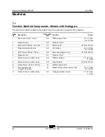
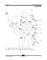
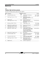
Страница 94: ...241 3 bar AC System relief 25 ft lbs 34 Nm 4 Proportional solenoid valve AD All functions 46 54 ft lbs 62 73 Nm 5 Relief valve 2000 psi 138 bar AE Steer and outrigger circuit 50 ft lbs 68 Nm 6 Diagnos...

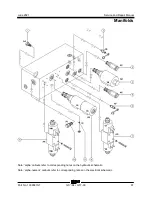
Страница 95: ...d Repair Manual Manifolds Part No 1306587GT GS 84 GS 90 81 Note alpha callouts refer to corresponding notes on the hydraulic schematic Note alpha numeric callouts refer to corresponding notes on the e...

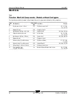
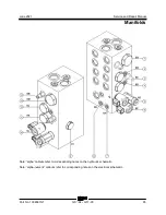
Страница 96: ...port AB Pressure Circuit 3 Relief valve 3500 psi 241 3 bar AC System relief 25 ft lbs 34 Nm 4 Proportional solenoid valve AD All functions 46 54 ft lbs 62 73 Nm 5 Relief valve 2000 psi 138 bar AE Ste...

Страница 97: ...d Repair Manual Manifolds Part No 1306587GT GS 84 GS 90 83 Note alpha callouts refer to corresponding notes on the hydraulic schematic Note alpha numeric callouts refer to corresponding notes on the e...

Страница 98: ...noid Valve 2 position 3 way EF 2 speed motor shift circuit 20 ft lbs 27 Nm 7 Orifice Plug 0 035 inch 0 9 mm EG Brake circuit 8 Orifice Plug 0 045 inch 1 1 mm EH 2 speed motor shift circuit 9 Shuttle v...

Страница 99: ...d Repair Manual Manifolds Part No 1306587GT GS 84 GS 90 85 Note alpha callouts refer to corresponding notes on the hydraulic schematic Note alpha numeric callouts refer to corresponding notes on the e...

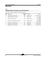
Страница 100: ...A Oscillate circuit 45 ft lbs 61 Nm 2 Relief valve 3500 psi 241 3 bar DB System relief 25 30 ft lbs 34 41 Nm 3 Relief valve 900 psi 62 bar DC Float circuit relief 25 30 ft lbs 34 41 Nm 4 Priority flow...

Страница 101: ...d Repair Manual Manifolds Part No 1306587GT GS 84 GS 90 87 Note alpha callouts refer to corresponding notes on the hydraulic schematic Note alpha numeric callouts refer to corresponding notes on the e...

Страница 102: ...08 122 Nm 2 Orifice 0 030 inch 76 mm FB Delays shift to drive 35 40 ft lbs 47 54 Nm 3 Solenoid Valve 2 position 3 way FC Pilot valve to diverter 35 40 ft lbs 47 54 Nm 4 Relief valve 270 psi 18 6 bar F...

Страница 103: ...he test weight for your machine Refer to the specifications below Rated work load at full height maximum GS 3384 and GS 3390 2500 lbs 1135 kg GS 4390 most models refer to capacity indicator decal 1500...

Страница 104: ...just the internal hex socket Turn it counterclockwise to decrease the pressure Install the relief valve cap 19 Start the engine 20 Repeat this procedure beginning with step 15 21 Turn the machine off...

Страница 105: ...ection indicated by the blue arrow on the platform controls and observe the pressure reading on the pressure gauge Refer to Specifications Hydraulic Components Specifications Component damage hazard D...

Страница 106: ...ntrols Index No Description Schematic Item Function Torque 1 Solenoid operated 2 position 3 way directional valve AL Generator on off 25 ft lbs 34 Nm 2 Flow regulator valve 4 3 gpm 16 3 L min AM Gener...

Страница 107: ...uld activate and the engine should go to high rpm 4 Connect an electrical tool which does not draw more than 15A to the electrical outlet at the platform controls and run the tool at full speed 5 Conn...

Страница 108: ...e Manifold Components The generator relief valve manifold is located in the hydraulic manifold compartment Index No Description Schematic Item Function Torque 1 Relief valve 3500 psi 241 bar AR Genera...

Страница 109: ...he coil resistance using a multimeter set to resistance Refer to the Valve Coil Resistance Specification table Result If the resistance is not within the adjusted specification plus or minus 10 replac...

Страница 110: ...the coil Resistor 10 Genie part number 27287 Note The battery should read 9V DC or more when measured across the terminals 1 multimeter 2 9v DC battery 3 10 resistor 4 coil Note Dotted lines in illus...

Страница 111: ...feet 5 5 m from the ground 3 Release the safety arm latch lift the safety arm and rotate to a vertical position Lock the safety arm in position Note Be sure that the safety arm is locked in the verti...

Страница 112: ...ate the hydraulic fluid during operation It utilizes internal suction strainers for the pump supply lines and has an external return line filter with a filter condition indicator How to Remove the Hyd...

Страница 113: ...l of the condition 9 Remove the drain plug from the hydraulic tank and completely drain the tank into a suitable container Refer to Specifications Machine Specifications Bodily injury hazard Spraying...

Страница 114: ...d wheel assembly 6 Remove the hose clamps retaining fasteners from the drive motor guard Remove the hose clamps 7 Remove the retaining fasteners from the drive motor guard Remove the drive motor guard...

Страница 115: ...chine 4 Raise the machine approximately 2 inches 5 cm Place blocks under the chassis for support Crushing hazard The chassis will fall if not properly supported 5 Remove the wheel lug bolts Remove the...

Страница 116: ...in Note While removing the pin retaining fasteners take note of the quantity and location of the spacers when removing the pivot pin 4 Remove the steer cylinder from the machine 9 3 Oscillating Axle O...

Страница 117: ...be lost Terminal 86 of K12 receives power from pin J1 A4 while driving is engaged and the ECM is powered J1 A4 is disabled when an outrigger is lowered to the ground Oscillate Limit Switches S50 S51...

Страница 118: ...and Fitting Torque Specifications 1 Block the steer wheels 2 Tag disconnect and plug the hydraulic hoses from the drive motor and brake Cap the fittings on the drive motor and brake Bodily injury haz...

Страница 119: ...ty under the drive chassis at the steer end of the machine 3 Loosen the wheel lug nuts Do not remove them 4 Raise the machine approximately 2 inches 5 cm Place blocks under the chassis for support Cru...

Страница 120: ...Service and Repair Manual June 2021 Non steer Axle Components 106 GS 84 GS 90 Part No 1306587GT 10 3 Oscillating Axle Refer to Repair Procedure Oscillating Axle Option GS 90 Models...

Страница 121: ...ng from the outrigger cylinder solenoid valve 4 Tag disconnect and plug the hydraulic hoses from the outrigger cylinder Cap the fittings on the cylinder Bodily injury hazard Spraying hydraulic oil can...

Страница 122: ...with all weight tools and equipment removed from the platform Note Perform this procedure in an area that is free of overhead obstructions 1 Models with outriggers Fully lower the outriggers and leve...

Страница 123: ...form has reached full height momentarily activate the calibration toggle switch in the up position to confirm 12 Fully lower the platform to the stowed position Note The platform will lower and automa...

Страница 124: ...Emergency Stop button to the on position at the platform controls 2 Press and hold both the blue platform up and yellow platform down buttons Pull out the red Emergency Stop button to the on position...

Страница 125: ...sition 6 Measure the distance between the surface and the platform floor Model Measurement GS 3384 GS 3390 93 102 inches 236 259 cm GS 4390 112 124 inches 284 315 cm GS 5390 133 143 inches 338 363 cm...

Страница 126: ...structions in the appropriate operator s manual on your machine Be sure that all necessary tools and test equipment are available and ready for use Read each appropriate fault code thoroughly Attempti...

Страница 127: ...ols and certain pieces of test equipment are required voltmeter ohmmeter pressure gauges LED Diagnostic Readout The diagnostic readout displays numerical codes that provide information about the machi...

Страница 128: ...FAULT Red Left turn switch fault Malfunctioning steer left microswitch Troubleshoot steer left microswitch 26 RIGHT TURN SW FAULT Red Right turn switch fault Malfunctioning steer right microswitch Tro...

Страница 129: ...e button fault at platform controls Outriggers disabled Troubleshoot button OR replace printed circuit board at platform controls 3812 OSCILLATE LIMIT SWITCHES Red Value to high Voltage above 3000 mV...

Страница 130: ...d Troubleshoot coil OR wiring 58 BRAKE COIL FAULT Red Brake release coil Y2 fault Brakes will not release Troubleshoot coil OR wiring 60 FORWARD 1 COIL FAULT Red Forward 1 coil Y6 fault Drives slow or...

Страница 131: ...OTRG COIL FLT Red Right front outrigger coil Y36 fault Right front outrigger function inhibited Troubleshoot coil OR wiring 83 RIGHT REAR OTRG COIL FLT Red Right rear outrigger coil Y34 fault Right r...

Страница 132: ...Overload Display 1 LCD screen 2 red LED The diagnostic readout displays numerical codes that provide information about height sensor pressure sensor and platform overload malfunctions The codes listed...

Страница 133: ...ent or correlated signals Check wiring Shorted to high or low Replace sensor 15 Value too low Output lower than normal Check wiring Check 5V supply voltage Check ground Open or short circuit Replace s...

Страница 134: ...eplace sensor 15 Value too low Output lower than normal Check wiring Check 5V supply voltage Check ground Open or short circuit Replace sensor 16 Value at 0 V Output at 0 volts Check wiring Open circu...

Страница 135: ...ow Replace sensor 15 Value too low Output lower than normal Check wiring Check 5V supply voltage Check ground Open or short circuit Replace sensor 16 Value at 0 V Output at 0 volts Check wiring Open c...

Страница 136: ...ersion mismatch Primary and secondary processors software do not match Update software Replace SCON 76 Platform Overload 23 Too high Platform overloaded Remove weight from platform 79 DISCON Display c...

Страница 137: ...urs that does not result in an engine shutdown the engine rpm will go into limp home mode resulting in the loss of high rpm When operating from the platform if the red Emergency Stop button is pushed...

Страница 138: ...curs that does not result in an engine shutdown the engine rpm will go into limp home mode resulting in the loss of high rpm When operating from the platform if the red Emergency Stop button is pushed...

Страница 139: ...vice Solid fault acknowledged Contact service 2 Left red LED Flashing engine fault detected Contact service Flashing with right flashing amber LED engine soot level over 140 Engine shut down Contact s...

Страница 140: ...T Soft Key Functions and Icons Deutz D 2 9 L4 Models Soft Key Functions and Icons Deutz D 2 9 L4 Models 1 Next menu Exit Back one screen Decrease brightness 2 Brightness Contrast Scroll up Increase In...

Страница 141: ...e brightness 3 Scroll down Decrease Time Date Increase brightness 4 Main menu Select Main Screen Icons Engine Warning Icons Engine RPM Voltage Oil pressure Coolant temperature Regen required DPF servi...

Страница 142: ...Service and Repair Manual June 2021 Fault Code Display Deutz Models 128 GS 84 GS 90 Part No 1306587GT Main Menu Structure Deutz D 2 9 L4 Models Main Menu Structure Deutz D 2 9 L4 Models...

Страница 143: ...June 2021 Service and Repair Manual Fault Code Display Deutz Models Part No 1306587GT GS 84 GS 90 129 Main Menu Structure Deutz TD 2 2 L3 Models Main Menu Structure Deutz TD 2 2 L3 Models...

Страница 144: ...Valve Overload by short circuit 51 7 1016 Actuator position for EGR Valve not plausible SPN FMI KWP Description 51 11 1231 Actuator error EGR Valve Power stage over temp due to high current 51 12 101...

Страница 145: ...ad correction factor exceeding the maximum drift limit 157 3 877 Sensor error rail pressure signal range check high 157 4 878 Sensor error rail pressure signal range check low SPN FMI KWP Description...

Страница 146: ...1 4 381 Physical range check low for EGR differential pressure 411 4 796 Sensor error differential pressure Venturiunit EGR signal range check low SPN FMI KWP Description 412 3 1007 Sensor error EGR c...

Страница 147: ...eout Error of CAN Receive Frame TSC1TE Setpoint 1079 13 946 Sensor supply voltage monitor 1 error ECU 1080 13 947 Sensor supply voltage monitor 2 error ECU SPN FMI KWP Description 1109 2 121 Engine sh...

Страница 148: ...25 Physical range check low for EGR exhaust gas mass flow 2659 2 1523 Exhaust gas recirculation AGS sensor plausibility error SPN FMI KWP Description 2659 2 1527 AGS sensor temperature exhaust gas mas...

Страница 149: ...009 9 825 Pressure Relief Valve PRV reached maximun allowed opening count 523009 10 833 Pressure relief valve PRV reached maximun allowed open time SPN FMI KWP Description 523212 9 171 Timeout Error o...

Страница 150: ...ction reported error 523612 12 628 Internal ECU monitoring detection reported error SPN FMI KWP Description 523612 12 637 Internal ECU monitoring detection reported error 523612 12 1170 Internal softw...

Страница 151: ...N Description 523788 12 299 Timeout Error of CAN Transmit Frame TrbCH Status Wastegate 523793 9 202 Timeout Error of CAN Receive Frame UAA10 AGS sensor service message 523794 9 203 Timeout Error of CA...

Страница 152: ...36 12 169 Timeout Error of CAN Transmit Frame EEC3VOL2 Engine send messages 523946 0 1158 Zero fuel calibration injector 1 in firing order maximum value exceeded SPN FMI KWP Description 523946 1 1164...

Страница 153: ...value downstream DOC too high 524028 2 1431 CAN message PROEGRActr plausibility error 524029 2 1432 Timeout Error of CAN Receive Frame ComEGRActr exhaust gas recirculation positioner 524030 7 1440 EGR...

Страница 154: ...ut error of CAN Transmit Frame ComETVActr 524111 9 1680 Timeout error of CAN Receive Frame ComRxETVActr 524112 9 1671 Timeout ComITVActr 524113 9 1681 Timeout error of CAN Receive Frame ComRxITVActr S...

Страница 155: ...ntial pressure 1075 411 2 Engine exhaust gas recirculation Positive measured differential pressure DTC SPN FMI Description 1077 411 3 Engine exhaust gas recirculation Signal value above maximum limit...

Страница 156: ...e normal or shorted to high 1131 1209 4 Engine exhaust pressure sensor voltage below normal or shorted to low DTC SPN FMI Description 1134 3251 3 DPF voltage above normal or shorted to high 1135 3251...

Страница 157: ...0 Maximum rail pressure exceeded in limp home mode 1208 157 3 Engine fuel injector metering rail pressure voltage above normal or shorted to high DTC SPN FMI Description 1209 157 4 Engine fuel injecto...

Страница 158: ...CU below normal operational range 1306 677 3 Engine starter motor relay voltage above normal or shorted to high 1307 677 4 Engine starter motor relay voltage below normal or shorted to low DTC SPN FMI...

Страница 159: ...e valve 1 position 1 mechanical system not responding or out of adjustment Valve stuck open 1391 51 3 Engine throttle valve 1 position 1 voltage above normal or shorted to high DTC SPN FMI Description...

Страница 160: ...ror of CAN receive frame TSC1AR Retarder 365 3349 0 Timeout error of CAN receive frame TSC1TE Setpoint DTC SPN FMI Description 367 3349 0 Timeout Error of CAN receive frame TSC1TR control signal 38 14...

Страница 161: ...threshold Overrun Mode 610 171 15 Environment temperature sensor temperature above upper physical threshold DTC SPN FMI Description 613 171 3 Ambient air temperature sensor voltage above normal or sh...

Страница 162: ...Engine cylinder 4 fuel injection quantity current below normal or open circuit 820 5362 5 Engine cylinder 5 fuel injection quantity current below normal or open circuit DTC SPN FMI Description 821 536...

Страница 163: ...gramming injector 1 839 2798 14 Engine fuel 1 injector group 2 missing injector adjustment value programming injector 2 DTC SPN FMI Description 840 4257 14 Engine fuel 1 injector group 3 missing injec...

Страница 164: ...ers Diagnostic fault check to report the error due to injection quantity correction 884 5442 2 Engine fuel injection pressure error for multiple cylinders 885 29 2 Accelerator pedal 2 position 886 677...

Страница 165: ...fault codes are displayed the check engine light will blink a code 1 6 5 4 three times After the fault codes the check engine light will blink a code 1 6 5 4 three times again indicating the end of t...

Страница 166: ...221 TPS1 higher than TPS2 222 TPS2 low voltage 223 TPS2 high voltage 236 TIP Active Code Description 237 TIP Low Voltage 238 TIP High Voltage 261 Injector Loop Open or Low side short to Ground 262 Inj...

Страница 167: ...coil open 628 FPump motor loop open or high side shorted to ground 628 Fpump relay control ground short 629 FPump motor high side shorted to power 629 Fpump relay coil short to power Code Description...

Страница 168: ...than expected 1 1522 CHT higher than expected 2 1531 IVS Brake Trans Park interlock failure 1541 AUX analog PUD1 high 1542 AUX analog PUD1 low 1543 AUX analog PUD2 high 1544 AUX analog PUD2 low 1545 A...

Страница 169: ...ltage and FPP2 disagrees with IVS 2121 FPP1 lower than FPP2 2122 FPP1 high voltage 2123 FPP1 low voltage 2125 FPP2 invalid voltage and FPP1 disagrees with IVS 2126 FPP1 higher than FPP2 2127 FPP2 low...

Страница 170: ...Loop Open or Low side Short to Ground 2316 Primary Coil Shorted 2318 Primary Loop Open or Low side Short to Ground 2319 Primary Coil Shorted 2321 Primary Loop Open or Low side Short to Ground 2322 Pr...

Страница 171: ...afety rules and operating instructions in the appropriate operator s manual on your machine Be sure that all necessary tools and test equipment are available and ready for use About This Section There...

Страница 172: ...ith amperage Circuit breaker with amperage Connection no terminal Circuits crossing no connection Quick disconnect terminal Level sensor without outriggers Power relay Coil solenoid or relay Contact s...

Страница 173: ...3 position 4 way directional valve Solenoid operated 3 position 5 way directional valve Solenoid operated 2 position 3 way directional valve Solenoid operated 2 position 2 way directional valve Filte...

Страница 174: ...uF CB Circuit breaker CB2 System power 20A CB6 Controls 7A CB7 Throttle 25A Deutz models Item Description FB1 Flashing beacon option G Gauge G6 Hour meter GND Ground H Horn or alarm H1 Alarm PCON H2 A...

Страница 175: ...5 Left front outrigger Y36 Right front outrigger Y39 Outrigger retract Y40 Outrigger extend Y51 Electronic displacement control Y93 Left oscillate Y94 Right oscillate Y95 Oscillate float Y100 Oscillat...

Страница 176: ...87GT Ford MSG 425 EFI 1 Power Relay 2 Fuel Pump Relay 3 Empty 4 Starter 20A 5 Fuse 1 10A Battery voltage to EPR 6 Fuse 2 5A Ignition voltage to GCP and relays 7 Fuse 3 10A Battery voltage to GCP 8 Fus...

Страница 177: ...No 1306587GT GS 84 GS 90 163 1 drive pump 2 engine 3 outriggers 4 pressure sensor 5 angle sensor 6 SCON 7 platform controls 8 flashing beacon 9 ECM Electronic Control Module 10level sensor 11horn 12g...

Страница 178: ...rtional coil Y9 output B5 Right front outrigger coil Y36 output B6 Outrigger extend coil Y40 output B7 Outrigger retract coil Y39 output B8 Plug B9 Left front outrigger coil Y35 output B10 Left rear o...

Страница 179: ...S8 blue input B2 Level sensor S8 black input B3 Level sensor S8 yellow input B4 Plug B5 Plug B6 Plug B7 Engine start relay CR1 terminal 86 output B8 Ignition relay CR8 terminal 86 output B9 Engine hi...

Страница 180: ...Part No 1306587GT K1 1st E Stop K2 2nd E Stop K3 Starter K4 Ignition K5 Horn K6 Auxiliary down K8 Oil cooler option K11 Oscillate stowed option K12 Oscillate elevated option K15 Descent overload K16 C...

Страница 181: ...June 2021 Service and Repair Manual Wiring Diagram Platform Control Box Part No 1306587GT GS 84 GS 90 167...

Страница 182: ...1 outrigger deployed all models left front LS12 right front LS13 left rear LS14 right rear LS15 2 outrigger deployed GS 5390 CE models lower left front LS12A right front LS13A left rear LS14A right re...

Страница 183: ...June 2021 Service and Repair Manual Wiring Diagram 12 kW Hydraulic Generator option Part No 1306587GT GS 84 GS 90 169...

Страница 184: ...gh RPM 2 The SX controller is turned ON supplying power to the bypass valve and the change over relay The EDC valve is switched over to the output of the SX controller 3 When the AC generator is turne...

Страница 185: ...June 2021 Service and Repair Manual 171 Ford MSG 425 Engine Wire Harness...

Страница 186: ...Service and Repair Manual June 2021 172 GS 84 GS 90 Part No 1306587GT Ford MSG 425 EFI Engine Wire Harness...

Страница 187: ...June 2021 Service and Repair Manual Part No 1306587GT GS 84 GS 90 173 Deutz D 2 9 L4 Engine Wire Harness...

Страница 188: ...Service and Repair Manual June 2021 174 Deutz D 2 9 L4 Engine Wire Harness...

Страница 189: ...June 2021 Service and Repair Manual 175 Deutz TD 2 2 L3 Engine Wire Harness...

Страница 190: ...Service and Repair Manual June 2021 176 GS 84 GS 90 Part No 1306587GT Deutz TD 2 2 L3 Engine Wire Harness...

Страница 191: ...June 2021 Service and Repair Manual Part No 1306587GT GS 84 GS 90 177 Deutz TD 2 2 L3 Engine Wire Harness...

Страница 192: ...Service and Repair Manual June 2021 178 Deutz TD 2 2 L3 Engine Wire Harness...

Страница 193: ...June 2021 Service and Repair Manual 179 Hydraulic Schematic...

Страница 194: ...Service and Repair Manual June 2021 180 GS 84 GS 90 Part No 1306587GT Hydraulic Schematic...

Страница 195: ...June 2021 Service and Repair Manual Part No 1306587GT GS 84 GS 90 181 Hydraulic Schematic...

Страница 196: ...Service and Repair Manual June 2021 182 Hydraulic Schematic...

Страница 197: ...June 2021 Service and Repair Manual 183 Electrical Schematic Ford Engine Models ANSI CSA...

Страница 198: ...Service and Repair Manual June 2021 184 GS 84 GS 90 Part No 1306587GT Electrical Schematic Ford Engine Models ANSI CSA...

Страница 199: ...June 2021 Service and Repair Manual Part No 1306587GT GS 84 GS 90 185 Electrical Schematic Ford Engine Models ANSI CSA...

Страница 200: ...Service and Repair Manual June 2021 186 Electrical Schematic Ford Engine Models ANSI CSA...

Страница 201: ...June 2021 Service and Repair Manual 187 Electrical Schematic Deutz Engine Models ANSI CSA...

Страница 202: ...Service and Repair Manual June 2021 188 GS 84 GS 90 Part No 1306587GT Electrical Schematic Deutz Engine Models ANSI CSA...

Страница 203: ...June 2021 Service and Repair Manual Part No 1306587GT GS 84 GS 90 189 Electrical Schematic Deutz Engine Models ANSI CSA...

Страница 204: ...Service and Repair Manual June 2021 190 Electrical Schematic Deutz Engine Models ANSI CSA...

Страница 205: ...June 2021 Service and Repair Manual Part No 1306587GT GS 84 GS 90 191 Electrical Schematic SCON ANSI CSA...

Страница 206: ...Service and Repair Manual June 2021 192 Electrical Schematic SCON ANSI CSA...

Страница 207: ...June 2021 Service and Repair Manual 193 Electrical Schematic Ford Engine Models AS CE...

Страница 208: ...Service and Repair Manual June 2021 194 GS 84 GS 90 Part No 1306587GT Electrical Schematic Ford Engine Models AS CE...

Страница 209: ...June 2021 Service and Repair Manual Part No 1306587GT GS 84 GS 90 195 Electrical Schematic Ford Engine Models AS CE...

Страница 210: ...Service and Repair Manual June 2021 196 Electrical Schematic Ford Engine Models AS CE...

Страница 211: ...June 2021 Service and Repair Manual 197 Electrical Schematic Deutz Engine Models AS CE...

Страница 212: ...Service and Repair Manual June 2021 198 GS 84 GS 90 Part No 1306587GT Electrical Schematic Deutz Engine Models AS CE...

Страница 213: ...June 2021 Service and Repair Manual Part No 1306587GT GS 84 GS 90 199 Electrical Schematic Deutz Engine Models AS CE...

Страница 214: ...Service and Repair Manual June 2021 200 Electrical Schematic Deutz Engine Models AS CE...

Страница 215: ...June 2021 Service and Repair Manual Part No 1306587GT GS 84 GS 90 201 Electrical Schematic SCON AS CE...

Страница 216: ...Service and Repair Manual June 2021 202 Electrical Schematic SCON AS CE GS 84 GS 90 Part No 1306587GT Service and Repair Manual June 2021...

Страница 217: ......
Отзывы: