June 2021
Service and Repair Manual
Ground Controls
Part No. 1306587GT
GS
™
-84 • GS
™
-90
59
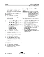
8 Press the yellow platform down button to
decrease the drive speed or press the blue
platform up button to increase the drive
speed. Refer to Specifications,
Performance
Specifications.
Note: The performance achieved should always be
within specifications.
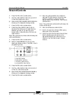
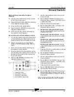
9 Press the lift function enable button.
Result: TUNE SPEEDS is showing in the
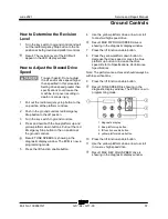
diagnostic display window. The ECM is now in
programming mode.
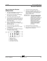
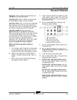
1 diagnostic display
2 blue platform up button
3 lift function enable button
4 yellow platform down button
10 Press the lift function enable button.
11 Use the yellow platform down arrow to scroll
to max rev high torque drive.
Result: MAX REV HIGH TORQUE DRIVE is
showing in the diagnostic display window.
12 Press the lift function enable button.
13 Press the yellow platform down button to
decrease the drive speed or press the blue
platform up button to increase the drive
speed. Refer to Specifications,
Performance
Specifications.
Note: The performance achieved should always be
within specifications.
14 Press the lift function enable button.
15 Push in the ground controls red Emergency
Stop button to the off position.
How to Adjust the Raised Drive Speed
How to Adjust the Raised Drive
Speed
Tip-over hazard. Do not adjust
the lift and/or drive speed higher
than specified in this procedure.
Setting drive speed greater than
specifications could cause the
machine to tip over resulting in
death or serious injury.
Note: The GS-5390 will not drive with the platform
raised above 33 feet / 10,1 m.
1 Pull out the red Emergency stop button to the
on position at the platform controls.
2 Push in the ground controls red Emergency
Stop button to the off position.
3 Turn the key switch to ground controls.
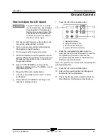
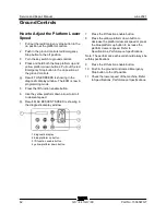
4 Press and hold both the blue platform up and
yellow platform down buttons. Pull out the red
Emergency Stop button to the on position at
the ground controls.
Result: TUNE SPEEDS is showing in the
diagnostic display window. The ECM is now in
programming mode.
Содержание Genie GS-3384
Страница 93: ...June 2021 Service and Repair Manual Part No 1306587GT GS 84 GS 90 79 This page intentionally left blank...
Страница 181: ...June 2021 Service and Repair Manual Wiring Diagram Platform Control Box Part No 1306587GT GS 84 GS 90 167...
Страница 183: ...June 2021 Service and Repair Manual Wiring Diagram 12 kW Hydraulic Generator option Part No 1306587GT GS 84 GS 90 169...
Страница 185: ...June 2021 Service and Repair Manual 171 Ford MSG 425 Engine Wire Harness...
Страница 186: ...Service and Repair Manual June 2021 172 GS 84 GS 90 Part No 1306587GT Ford MSG 425 EFI Engine Wire Harness...
Страница 187: ...June 2021 Service and Repair Manual Part No 1306587GT GS 84 GS 90 173 Deutz D 2 9 L4 Engine Wire Harness...
Страница 188: ...Service and Repair Manual June 2021 174 Deutz D 2 9 L4 Engine Wire Harness...
Страница 189: ...June 2021 Service and Repair Manual 175 Deutz TD 2 2 L3 Engine Wire Harness...
Страница 190: ...Service and Repair Manual June 2021 176 GS 84 GS 90 Part No 1306587GT Deutz TD 2 2 L3 Engine Wire Harness...
Страница 191: ...June 2021 Service and Repair Manual Part No 1306587GT GS 84 GS 90 177 Deutz TD 2 2 L3 Engine Wire Harness...
Страница 192: ...Service and Repair Manual June 2021 178 Deutz TD 2 2 L3 Engine Wire Harness...
Страница 193: ...June 2021 Service and Repair Manual 179 Hydraulic Schematic...
Страница 194: ...Service and Repair Manual June 2021 180 GS 84 GS 90 Part No 1306587GT Hydraulic Schematic...
Страница 195: ...June 2021 Service and Repair Manual Part No 1306587GT GS 84 GS 90 181 Hydraulic Schematic...
Страница 196: ...Service and Repair Manual June 2021 182 Hydraulic Schematic...
Страница 197: ...June 2021 Service and Repair Manual 183 Electrical Schematic Ford Engine Models ANSI CSA...
Страница 198: ...Service and Repair Manual June 2021 184 GS 84 GS 90 Part No 1306587GT Electrical Schematic Ford Engine Models ANSI CSA...
Страница 199: ...June 2021 Service and Repair Manual Part No 1306587GT GS 84 GS 90 185 Electrical Schematic Ford Engine Models ANSI CSA...
Страница 200: ...Service and Repair Manual June 2021 186 Electrical Schematic Ford Engine Models ANSI CSA...
Страница 201: ...June 2021 Service and Repair Manual 187 Electrical Schematic Deutz Engine Models ANSI CSA...
Страница 202: ...Service and Repair Manual June 2021 188 GS 84 GS 90 Part No 1306587GT Electrical Schematic Deutz Engine Models ANSI CSA...
Страница 203: ...June 2021 Service and Repair Manual Part No 1306587GT GS 84 GS 90 189 Electrical Schematic Deutz Engine Models ANSI CSA...
Страница 204: ...Service and Repair Manual June 2021 190 Electrical Schematic Deutz Engine Models ANSI CSA...
Страница 205: ...June 2021 Service and Repair Manual Part No 1306587GT GS 84 GS 90 191 Electrical Schematic SCON ANSI CSA...
Страница 206: ...Service and Repair Manual June 2021 192 Electrical Schematic SCON ANSI CSA...
Страница 207: ...June 2021 Service and Repair Manual 193 Electrical Schematic Ford Engine Models AS CE...
Страница 208: ...Service and Repair Manual June 2021 194 GS 84 GS 90 Part No 1306587GT Electrical Schematic Ford Engine Models AS CE...
Страница 209: ...June 2021 Service and Repair Manual Part No 1306587GT GS 84 GS 90 195 Electrical Schematic Ford Engine Models AS CE...
Страница 210: ...Service and Repair Manual June 2021 196 Electrical Schematic Ford Engine Models AS CE...
Страница 211: ...June 2021 Service and Repair Manual 197 Electrical Schematic Deutz Engine Models AS CE...
Страница 212: ...Service and Repair Manual June 2021 198 GS 84 GS 90 Part No 1306587GT Electrical Schematic Deutz Engine Models AS CE...
Страница 213: ...June 2021 Service and Repair Manual Part No 1306587GT GS 84 GS 90 199 Electrical Schematic Deutz Engine Models AS CE...
Страница 214: ...Service and Repair Manual June 2021 200 Electrical Schematic Deutz Engine Models AS CE...
Страница 215: ...June 2021 Service and Repair Manual Part No 1306587GT GS 84 GS 90 201 Electrical Schematic SCON AS CE...
Страница 217: ......

