


Service and Repair Manual
May 2021
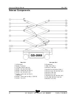
Scissor Components
24
GS
™
-2669 DC • GS
™
-3369 DC • GS
™
-4069 DC
Part No. 1306585GT
3-2 Scissor Assembly, GS-3369 DC
3-2
Scissor Assembly, GS-3369 DC
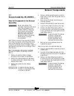
How to Disassemble the Scissor
Assembly
Bodily injury hazard. This
procedure requires specific repair
skills, lifting equipment and a
suitable workshop. Attempting
this procedure without these
skills and tools could result in
death or serious injury and
significant component damage.
Dealer service is strongly
recommended.
Note: When removing a hose assembly or fitting,
the O-ring (if equipped) on the fitting and/or hose
end must be replaced. All connections must be
torqued to specification during installation. Refer to
Specifications,
Hydraulic Hose and Fitting Torque
Specifications.
Note: This procedure will require an overhead
lifting device capable of supporting 1000 lbs /
454 kg.
1 Remove the platform. Refer to Repair
Procedure,
How to Remove the Platform
.
2 Remove the retaining fasteners that attach
the ladder to the drive chassis. Remove the
ladder and set aside.
3 Remove the cables from the linkage
assembly.
Component damage hazard.
Cables and hoses can be
damaged if they are kinked or
pinched.
4 Using an overhead lifting device attach a
4 hook sling chain to the ends of the number
4 inner arm. Make the chains tight but do not
apply lifting pressure.
Crushing hazard. The linkage
assembly could become
unbalanced and fall if not
properly supported when
removed from the machine.
5 Remove the retaining fasteners from the
number 4 pivot pins.
Note: Do not remove the external snap ring.
6 Using a soft metal drift, remove the pivot pins
and set aside.
7 Carefully lift the linkage assembly off of the
machine and place it on a structure capable of
supporting it.
8 Using a suitable supporting device, attach a
strap to the rod end of the lift cylinder. Do not
apply pressure.
9 Remove the lift cylinder rod end pivot pin
retaining fasteners
10 Using a soft metal drift, remove the pivot pin.
11 Lower the lift cylinder and remove the strap.
12 Using an overhead lifting device attach a
4 hook sling chain to the ends of the number
3 inner arm. Make the chains tight but do not
apply lifting pressure.
Crushing hazard. The linkage
assembly could become
unbalanced and fall if not
properly supported when
removed from the machine.
Содержание Genie GS-2669 DC
Страница 62: ...Service and Repair Manual May 2021 Manifolds 50 GS 2669 DC GS 3369 DC GS 4069 DC Part No 1306585GT ...
Страница 135: ...May 2021 Service and Repair Manual 123 use Ground and Platform Control Boxes Fuse Box Layout All Models ...
Страница 138: ...Service and Repair Manual May 2021 126 Ground Control Box Layout ...
Страница 140: ...Service and Repair Manual May 2021 128 Platform Control Box Layout ...
Страница 141: ...May 2021 Service and Repair Manual 129 Electrical Schematics Electrical Schematic ...
Страница 144: ...Service and Repair Manual May 2021 132 Electrical Schematic ...
Страница 145: ...May 2021 Service and Repair Manual 133 Hydraulic Schematics Hydraulic Schematic ...
Страница 147: ......


