background image


VEEK-MT-SoCKit User Manual


www.terasic.com


March 17, 2014 


20 


Demonstration Setup 


Make sure both Quartus II and Nios II are installed on the host PC 


Power on the SoCKit board 


Connect a USB cable to the USB-Blaster port on the SoCKit board and install the USB-Blaster 
II driver if necessary. 


Configure the FPGA by executing the demo batch file “test.bat” from the directory 
“SoCKit_Painter\demo_batch” (Note*) 


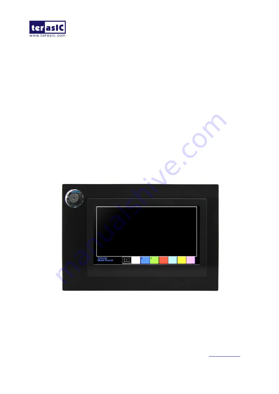
After the programming is downloaded and executed successfully, you will see a painter GUI 
displayed on the LCD. 

Figure 4-2 

shows the GUI of the Painter demo


The GUI is classified into three areas: Palette, Canvas, and Gesture. Users can select pen color 
from the color palette and start painting in the Canvas area. If a gesture is detected, the 
associated gesture symbol is shown in the gesture area. Click the “Clear” button to To clean up 
the content in the Canvas area. 


Figure 4-3 

shows the photo when users paint in the canvas area

Figure 4-4 

shows the photo 

when counter-clockwise rotation gesture is detected.


Figure 4-5

 shows the photo when zoom-in 

gesture is detected.


Figure 4-2 GUI of the Painter demo 

Содержание VEEK-MT-SoCKit

Страница 1: ...1 ...

Страница 2: ... 1 Using the SoCKit Main Board 11 3 2 Using the 7 LCD Capacitive Touch Screen 11 3 3 Using 5 megapixel Digital Image Sensor 13 3 4 Using the Digital Accelerometer 14 3 5 Using the Ambient Light Sensor 15 3 6 Using Terasic Multi touch IP 15 CHAPTER 4 VEEK MT SOCKIT DEMONSTRATIONS 18 4 1 System Requirements 18 4 2 Painter Demonstration 18 4 3 Camera Application 22 4 4 Digital Accelerometer Demonstra...

Страница 3: ...A as well as a capacitive LCD multimedia color touch panel which natively supports multi touch gestures A 5 megapixel digital image sensor ambient light sensor and 3 axis accelerometer make up the rich feature set The all in one embedded solution offered on the VEEK MT SoCKit a combination of LCD touch panel and digital image module provides embedded developers the ideal platform for multimedia ap...

Страница 4: ...y features are listed below 1 1 1 1 K Ke ey y F Fe ea at tu ur re es s SoCKit Main Board Cyclone V SX SoC 5CSXFC6D6F31C6N o Dual core ARM Cortex A9 HPS o 110K LEs 41509 ALMs o 5 140 M10K memory blocks o 224 18x18 Multiplier o 6 FPGA PLLs and 3 HPS PLLs o 2 Hard Memory Controllers o 3 125G Transceivers ...

Страница 5: ...icro USB type B connector o 10 100 1000 Ethernet Connectors o One HSMC 8 channel transceivers configurable I O standards 1 5 1 8 2 5 3 3V o One LTC connector One Serial Peripheral Interface SPI Master one I2C and one GPIO interface Display o 24 bit VGA DAC o 128x64 dots LCD Module with backlight Audio o 24 bit CODEC Line in Line out and Microphone in jacks Switches Buttons and LEDs o 8 User Keys F...

Страница 6: ... 480 dot Dot pitch 0 1926 H x0 1790 V mm Active area 154 08 H x 85 92 V mm Module size 164 9 H x 100 0 V x 5 7 D mm Surface treatment Glare Color arrangement RGB stripe Interface Digital 5 Megapixel Digital Image Sensor Superior low light performance High frame rate Global reset release which starts the exposure of all rows simultaneously Bulb exposure mode for arbitrary exposure times Snapshot mo...

Страница 7: ... Power 3 3V I O 1 7V 3 1V D Di ig gi it ta al l A Ac cc ce el le er ro om me et te er r o Up to 13 bit resolution at 16g o SPI 3 wire and 4 wire digital interface o Flexible interrupts modes A Am mb bi ie en nt t L Li ig gh ht t S Se en ns so or r o Approximates human eye response o Precise luminance measurement under diverse lighting conditions o Programmable interrupt function with user defined ...

Страница 8: ...e are two ways to install the License The first one is to add the path of license file license_multi_touch dat in Quartus II as shown in Figure 1 2 Figure 1 2 License setup The other one is to add license content to the existing license file The procedures are listed below 1 Use Notepad or other text editing software to open the file license_multi_touch dat 2 The license contains the FEATURE lines...

Страница 9: ... the link http cd veek mt sockit terasic com Table 1 3 shows the content of System CD Table 1 3 Directory of the System CD Folder Name Description Datasheet Datasheet for the major components on the kit Demonstrations FPGA and SoC reference codes IP touch screen IP License License of touch screen IP User_Manaual User Manual this manual 1 1 4 4 G Ge et tt ti in ng g H He el lp p Here is the contact...

Страница 10: ...CKit including block diagram and components 2 2 1 1 L La ay yo ou ut t a an nd d C Co om mp po on ne en nt ts s The picture of the VEEK MT SoCKit is shown in Figure 2 1 and Figure 2 2 It depicts the layout of the board and indicates the locations of connectors and key components Figure 2 1 VEEK MT SoCKit PCB and component diagram top view ...

Страница 11: ...lock diagram of the VEEK MT SoCKit board VEEK MT SoCKit is a combination of Cyclone V GX SoC development board and a Multi touch LCD Camera Card MTLC connected via the HSMC connector MTLC module is not only equipped with a 7 LCD screen it also equips a 5 Megapixel digital image sensor module G sensor and Light sensor All these sensors connect to the FPGA device via the HSMC connector so they can b...

Страница 12: ...VEEK MT SoCKit User Manual www terasic com March 17 2014 10 Figure 2 3 Block diagram of VEEK MT SoCKit ...

Страница 13: ...n n The VEEK MT SoCKit features a 7 inch capacitive amorphous TFT LCD panel The LCD touch screen offers resolution of 800x480 to provide users the best display quality for developing applications The LCD panel supports 24 bit parallel RGB data interface The VEEK MT SoCKit is also equipped with a Touch controller which can read the coordinates of the touch points through the serial port interface o...

Страница 14: ...pw 13 th tvpw tvb 23th is fixed Vertical Back Porch tvb 10 th Vertical Front Porch tvfp 22 th Vertical Valid tvd 480 th DATA Setup time Tdsu 8 ns Hold time Tdsu 8 ns Table 3 2 Pin Assignment of the LCD Touch Panel Signal Name FPGA Pin No Description I O Standard LCD_B0 C4 LCD blue data bus bit 0 2 5V LCD_B1 D5 LCD blue data bus bit 1 2 5V LCD_B2 A3 LCD blue data bus bit 2 2 5V LCD_B3 A4 LCD blue d...

Страница 15: ... 5V LCD_RSTB B1 Global reset pin 2 5V LCD_SHLR B3 Left or Right Display Control 2 5V LCD_UPDN B2 Up Down Display Control 2 5V LCD_VSD B11 Vertical sync input 2 5V TOUCH _I2C_SCL F14 touch I2C clock 2 5V TOUCH _I2C_SDA F15 touch I2C data 2 5V TOUCH _INT_n B12 touch interrupt 2 5V 3 3 3 3 U Us si in ng g 5 5 m me eg ga ap pi ix xe el l D Di ig gi it ta al l I Im ma ag ge e S Se en ns so or r The VEE...

Страница 16: ...RA_SCLK AF9 Serial clock 2 5V CAMERA_TRIGGER C5 Snapshot trigger 2 5V CAMERA_SDATA AG7 Serial data 2 5V CAMERA_XCLKIN AJ2 External input clock 2 5V 3 3 4 4 U Us si in ng g t th he e D Di ig gi it ta al l A Ac cc ce el le er ro om me et te er r The VEEK MT SoCKit is equipped with a digital accelerometer sensor module The ADXL345 is a small thin and ultralow power consumption 3 axis accelerometer wi...

Страница 17: ...ssor where luminance ambient light level in lux is derived using an empirical formula to approximate the human eye response For more detailed information about this chip please refer to its datasheet which is available on manufacturer s website or under the datasheet folder of the system CD Table 3 5 Pin Names and Descriptions of the Ambient Light Sensor Module Signal Name FPGA Pin No Description ...

Страница 18: ...es a pre defined gesture ID defined in Table 3 7 If it is not a gesture it means a single touch is occurred and the relative X Y coordinates can be derived from oREG_X1 and oREG_Y1 Table 3 6 Interface Definitions of Terasic Multi touch IP Pin Name Direction Description iCLK Input Connect to 50MHz Clock iRSTN Input Connect to system reset signal iTRIG Input Connect to Interrupt Pin of Touch IC oREA...

Страница 19: ... South 0x18 South West 0x1A West 0x1C North West 0x1E Rotate Clockwise 0x28 Rotate Anti clockwise 0x29 Click 0x20 Double Click 0x22 Two Points Gesture North 0x30 North East 0x32 East 0x34 South East 0x36 South 0x38 South West 0x3A West 0x3C North West 0x3E Click 0x40 Zoom In 0x48 Zoom Out 0x49 Note The Terasic Multi touch IP can also be found under the IP folder from the system CD ...

Страница 20: ...stall the USB Blaster II driver Copy the entire folder with demonstrations from the VEEK MT SoCKit system CD to the host computer 4 4 2 2 P Pa ai in nt te er r D De em mo on ns st tr ra at ti io on n This section shows how to control the LCD and the touch controller to run a demo based on Qsys and Altera VIP Suite The demonstration also shows how multi touch gestures and single touch coordinates o...

Страница 21: ...Painter demonstration Demonstration Source Code Project directory System CD Demonstrations FPGA SoCKit_Painter Bit stream used Painter sof Nios II workspace System CD Demonstrations FPGA SoCKit_Painter software Demonstration Batch File Demo batch file directory System CD Demonstrations FPGA SoCKit_Painter demo_batch The folder includes the following files Batch file test bat and test_bashrc FPGA c...

Страница 22: ...successfully you will see a painter GUI displayed on the LCD Figure 4 2 shows the GUI of the Painter demo The GUI is classified into three areas Palette Canvas and Gesture Users can select pen color from the color palette and start painting in the Canvas area If a gesture is detected the associated gesture symbol is shown in the gesture area Click the Clear button to To clean up the content in the...

Страница 23: ...VEEK MT SoCKit User Manual www terasic com March 17 2014 21 Figure 4 3 Single touch painting Figure 4 4 Counter clockwise rotation gesture ...

Страница 24: ...ta to the FPGA which handles image processing and converts the data to RGB format to display on the LCD module The I2C Sensor Configuration module is used to configure the CMOS sensor module Figure 4 6 shows the block diagram of this demonstration After the configuration code is downloaded into the FPGA successfully the I2C Sensor Configuration block will initiate the CMOS sensor via I2C interface...

Страница 25: ... bit data width each The writing clock is same as the CMOS sensor pixel clock The reading clock is provided by the LCD Controller which is 33MHz Finally the LCD controller fetches the RGB data from the buffer and displays it on the LCD panel continuously Because the resolution and timing of the LCD is compatible with WVGA 800 480 the LCD controller generates the same timing and the frame rate can ...

Страница 26: ...0 is set to OFF the brightness of image will be increased as KEY1 is pressed If SW0 is set to ON the brightness of image will be decreased as KEY1 is pressed User can use SW3 to mirror lines of the image Please remember to press KEY0 to reset the circuit after SW3 is toggled Note execute the test bat under the folder SoCKit_Camera demo_batch will automatically download the sof file Table 4 1 summa...

Страница 27: ...or The LCD displays the interface of our game When tilting the VEEK MT SoCKit the ADXL345 measures the static acceleration of gravity In our Nios II software we compute the change of angle in the x axis and y axis and show the angle data on the LCD display The value of light sensor will change as the brightness changes around the light sensor Figure 4 8 shows the hardware system block diagram of t...

Страница 28: ...I workspace System CD Demonstrations FPGA SoCKit_G_sensor software Demonstration Batch File Demo batch file directory System CD Demonstrations FPGA SoCKit_G_sensor demo_batch The folder includes the following files Batch file G_sensor bat test_bashrc FPGA configuration file SoCKit_G_sensor sof Nios II program G_sensor elf Demonstration Setup Configure the FPGA by executing the demo batch file test...

Страница 29: ...G_sensor demo_batch test bat to download sof and elf files 4 4 5 5 V Vi id de eo o a an nd d I Im ma ag ge e P Pr ro oc ce es ss si in ng g f fo or r C Ca am me er ra a The Video and Image Processing VIP for the Camera Example Design demonstrates dynamic scaling and clipping of a standard definition video stream in RGB format and picture in picture mixing with the background layer The video stream...

Страница 30: ...d mixer functions at run time is also provided The video system is implemented using the Qsys system design tool This abstracted design tool provides an easy path to the system integration of video processing data path with NTSC or PAL video input VGA output and Nios II processor for configuration and control purposes The Video and Image Processing Suite MegaCore functions have common open Avalon ...

Страница 31: ...onents Demonstration Source Code Project directory System CD Demonstrations FPGA SoCKit_VIP_Camera Bit stream used SoCKit _VIP_Camera sof Nios II workspace VEEK_VIP_Camera software Demonstration Batch File Demo batch file directory System CD Demonstrations FPGA SoCKit_VIP_Camera demo_batch The folder includes the following files ...

Страница 32: ...e automatically Press KEY0 on the SoCKit board to reset the circuit Press KEY2 to stop run press KEY3 again to switch back to FREE RUN mode and you should be able to see whatever the camera captures on the VGA display User can use SW3 to mirror lines of the image Please remember to press KEY0 to reset the circuit after SW3 is toggled In the touch screen press and drag the video frame box will resu...

Страница 33: ...VEEK MT SoCKit User Manual www terasic com March 17 2014 31 Figure 4 11 Screenshot of the VIP camera demonstration ...

Страница 34: ...ch 17 2014 32 Chapter 5 Appendix 5 5 1 1 R Re ev vi is si io on n H Hi is st to or ry y Version Change Log V1 0 Initial Version 5 5 2 2 C Co op py yr ri ig gh ht t S St ta at te em me en nt t Copyright 2014 Terasic Technologies All rights reserved ...

Отзывы: