15
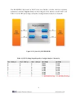
Table 3-5 SW2 Settings (Input Equalizer Configuration for Channel B)
Pin 4 SEL0_B
Pin 5 SEL1_B
Pin 6 SEL2_B
@1.25GHz
@2.5GHz
0
0
0
0.5dB
1.2 dB
0
0
1
0.6dB
1.5 dB
0
1
0
1.0 dB
2.6 dB
0
1
1
1.9 dB
4.3 dB
1
0
0
2.8 dB
5.8 dB
1
0
1
3.6 dB
7.1 dB
1
1
0
5.0 dB
9.0 dB
1
1
1
7.7 dB(Default Setting) 12.3 dB(Default Setting)
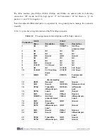
The SW2 pin 7 connects to the PI2EQX5904 RXD_A pin, while SW2 pin 8 connects to
PI2EQX5904 RXD_B pin. These 2 pins are used to control channel A & B Receiver Detect Enable
function. Automatic Receiver Detection is a feature that can set the number of active channels. By
sensing the presence of a load device on the output, the channel can be automatically enabled to
operate.
When setting the RXD_A or RXD_B to a high level, Automatic Receiver Detection will be enabled.
Please refer the datasheet of PI2EQX5904 for more settings.
Table 3-6 SW2
Settings (Receiver Detect Function Enable for CH_A & CH_B)
Pin 7 RXD_A
Pin 8 RXD_B
Receiver Detect Function Enable
1
1
CH_A & CH_B Receiver Detect
Enable (Default Setting)
1
0
CH_A Receiver Detect Enable
CH_B Receiver Detect Disable
0
1
CH_A Receiver Detect Disable
CH_B Receiver Detect Enable
0
0
CH_A & CH_B Receiver Detect
Disable
3
3
.
.
4
4
L
L
E
E
D
D
s
s
The PCA includes status LEDs, Please refer
Table 3-7
for the status of the LED indicator.
Board
Reference
LED name
Description
D1
CBL
Cable PRSNT1n
Содержание PCA
Страница 1: ......
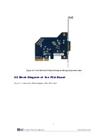
Страница 7: ...6 Figure 2 3 Block Diagram of PCA ...

