5.
LED indicators
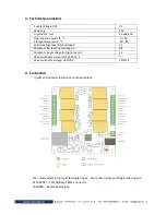
The following indicators show the status of the controller :
•
Relay status 1
÷
8
(green) – these LEDs are illuminated whenever the corresponding
relay is activated
•
Power
(red) – this flashes when the power supply is turned on;
•
Busy
(yellow) – this LED indicates that someone is connected to the controller
through web interface;
•
Link
(green) – this LED is located on the Ethernet connector. It indicates that the
device is connected to the network ;
•
Act
(yellow) – this LED is located on the Ethernet connector. It flashes when activity
is detected on the network.
6.
Example Application
6.1
Remote control
The controlled device is connected in series with the relay contacts. Users can operate
T
CW180
using a web browser or by using custom SNMP applications. The relay outputs are
managed independently of each other.

