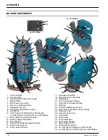
OPERATION
Tennant T3e (03--08)
7
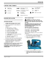
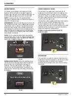
CONTROL PANEL SYMBOLS
Main Power
I/O Key Switch
Solution Flow
Control
Slow Speed
Brush Motor
Circuit Breaker
Fast Speed
FaST System I/O Switch
(FaST Model)
5% (3
°
) Maximum
Machine Climb
Activation Bail Direction
Brush Down Pressure
ec--H2O
System I/O Switch
(
ec--H2O
Model)
MACHINE INSTALLATION
UNCRATING MACHINE
1. Carefully check the shipping crate for signs of
damage. Report damages at once to carrier.
2. Check the contents list. Contact distributor for
missing items.
Contents:
D
2--12 V Batteries -- Optional
D
24V Battery Charger -- Optional
D
3--Foam Battery Spacers (#630375)
D
Battery Tray (#1012994)
D
38 cm Battery Cable (#130364)
D
4--Battery Cable Rubber Boots
D
1--FaST--PAK 365 Concentrate (#1017015)
(FaST Model)
D
Squeegee Assembly (#9001178)
D
Pad Driver -- Optional
Brushes and pads must be purchased separately.
3. To uncrate your machine, remove the shipping
hardware and straps that secure the machine to
the pallet. With assistance, carefully lift the
machine off the pallet.
ATTENTION: Do not roll machine off pallet unless a
ramp is used, machine damage may occur.
ATTENTION: To prevent possible machine damage,
install batteries after removing machine from
shipping pallet.
INSTALLING BATTERIES
WARNING: Fire Or Explosion Hazard.
Batteries Emit Hydrogen Gas. Keep Sparks And
Open Flame Away. Keep Battery Hood Open When
Charging.
FOR SAFETY: When servicing machine, wear
protective gloves and eye protection when
handling batteries and battery cables. Avoid
contact with battery acid.
Recommended Battery Specifications:
Two 12 volt deep cycle lead acid batteries.
105 AH battery -- 43cm Brush Assist Model
130 AH battery -- 50cm Brush Assist Model
155 AH battery -- 50cm Drive Model
Maximum battery dimensions: 174 mm W x 380 mm L
x 284 mm H.
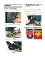
1. Park the machine on a level surface, remove the
key and set the parking brake if equipped.
2. Lift the recovery tank to access the battery
compartment (Figure 1).
FIG. 1
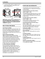
3. Carefully install the batteries into the battery
compartment tray and arrange the battery posts as
shown (Figure 2). Insert the foam spacers as
shown.

