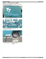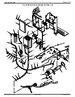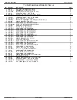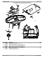
Page 2 of 16
KIT NO. 9014094
9014108 Rev. 01 (11- 2017)
Tennant Company
www.tennantco.com
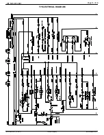
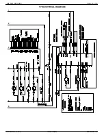
INSTALL ec-H2O WIRE HARNESS:
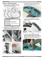
1. Using the below wire code diagram for reference,
route the ec-H2O wire harness [p/n 1074374] as
described in following steps (Figure 5).
A
B
C
D
E
F
A = ec-H2O Pump
B = Main Harness
C = C1 Capacitor
D = Negative Stand-off - Control Board
E = Main - Control Broad Contractor
F= ec-H2O LED
G = ec-H2O Water Conditioning Module Pump
H = Pressure Switch
I = ec-H2O Module
G
D
H
I
Fig. 5
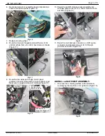
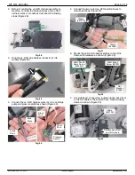
2. Starting from inside the battery compartment, route the
LED wires (F) under the solution tank and up the
steering column as shown. Route the wires through the
existing wire harness clamps (Figure 6).
E
Fig. 6
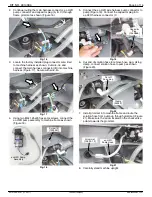
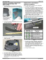
3. Re-install the steering column housing using the 4
mounting screws. Route the LED wires through the
small round hole as shown (Figure 7).
Fig. 7
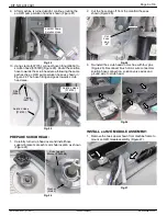
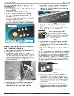
4. Using the control panel cover from the existing
instrument panel, assemble the following parts as
shown (Figure 8).
Gasket
[1052607]
LED Light
[1041822]
Panel
[1050592]
Control
Panel Cover
and Hinges
Fig. 8
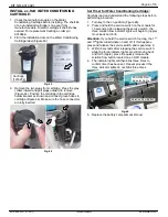
5. Connect the ec-H2O harness wires to LED light
(green to green, black to black and red to gray)
(Figure 9). Plug the existing wire connector into new
panel as shown. Using the existing mounting screws,
fasten new instrument panel to steering column
housing
Fig. 9


