


Page 3 of 16
KIT NO. 9014091
9014108 Rev. 01 (11- 2017)
Tennant Company
www.tennantco.com
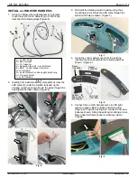
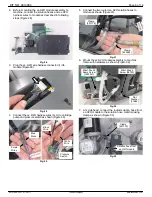
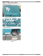
6. Reconnect wires to key switch panel components as
shown and replace panel (Figure 10).
Fig. 10
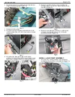
7. Replace steering wheel.
8. Route the main and negative stand-off wires (D, E)
under machine frame to control board area as shown
(Figure 11).
Fig. 11
9. Route the two wires up through control panel
grommet. Connect brown wire to main contactor and
black wire to negative stand- off terminal (Figure 12).
Brown wire to
Main Contactor
Black wire to
Negative Stand-off
Grommet
Fig. 12
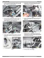
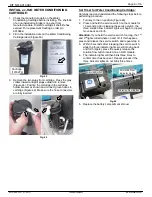
10. Route the ec-H2O module, pressure switch and
cartridge pump wires (G, H, I) under machine frame
as shown (Figure 13).
Fig. 13
11. Route the main harness connector, ec-H2O pump
connector and capacitor plug (A, B, C) through
grommet as shown (Figure 14).
Fig. 14
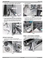
INSTALL ec-H2O PUMP ASSEMBLY:
1. On a level non- marring surface, with assistance,
carefully lay the machine on its right side (Figure 15).
Fig. 15


