background image

MAINTENANCE

515SS MM419 (4--96)

78

SIDE SWEEPING BRUSH

The side sweeping brush sweeps debris into the

path of the main brush. Check the side brush daily

for wear or damage. Remove any string or wire

found tangled on the side brush or side brush

drive hub.

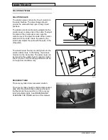
The side sweeping brush pattern should be

checked periodically. One-third of the side brush

bristles should contact the floor when the brush is

in motion. The side brush pattern adjustment is

made by moving the side brush up or down the

brush drive shaft.

The side sweeping brush should be replaced

when the remaining brush bristle measures 25

mm (1 in) or less in length.

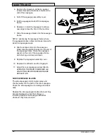
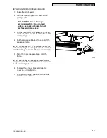
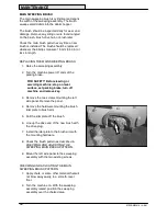
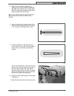
REPLACING THE SIDE SWEEPING BRUSH

1. Raise the sweeping assembly.

2. Turn the machine power off and set the

parking brake.

FOR SAFETY: Before leaving or

servicing machine; stop on level

surface, set parking brake, turn off

machine and remove key.

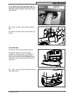
3. Remove the retaining hardware mounting

the side brush to the side brush drive shaft.

4. Slide the side brush off the side brush drive

shaft.

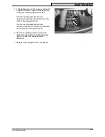
5. Slide the new side brush onto the side brush

drive shaft.

6. Mount the new side brush to the drive shaft

with the mounting hardware.

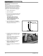
7. Check the side brush pattern. Adjust the

side brush with the side brush height on the

drive shaft, so that one-third of the bristles

contacts the floor when the brush is in

motion.

03376

10917

Содержание 515SS

Страница 1: ...515SS MM419 Rev 09 Operator Manual ...

Страница 2: ...g it This machine will provide excellent service However the best results will be obtained at minimum costs if D The machine is operated with reasonable care D The machine is maintained regularly per the maintenance instructions provided D The machine is maintained with TENNANT supplied or equivalent parts Manual Number MM419 Revision 09 Published 6 00 Copyright E 1996 1997 1998 1999 2000 TENNANT ...

Страница 3: ...STOP SCRUBBING 35 DRAINING AND CLEANING THE TANKS 36 STOP THE MACHINE 39 POST OPERATION CHECKLIST 40 OPERATION ON INCLINES 41 Page OPTIONS 42 VACUUM WAND 42 POWER WAND 46 MACHINE TROUBLESHOOTING 51 MAINTENANCE 54 MAINTENANCE CHART 54 LUBRICATION 56 PROPELLING GEARBOX 56 FRONT WHEEL SUPPORT BEARING 56 STEERING UNIVERSAL JOINT 56 SCRUB HEAD PARALLEL ARMS 57 REAR SQUEEGEE CASTER 58 STEERING GEAR CHAI...

Страница 4: ...BELT 81 STEERING GEAR CHAIN 81 STATIC DRAG CHAIN 82 BRAKES AND TIRES 83 BRAKES 83 TIRES 83 FRONT WHEEL 83 PUSHING TOWING AND TRANSPORTING THE MACHINE 84 PUSHING OR TOWING THE MACHINE 84 TRANSPORTING THE MACHINE 85 MACHINE JACKING 87 STORAGE INFORMATION 88 SPECIFICATIONS 89 GENERAL MACHINE PERFORMANCE 89 POWER TYPE 90 STEERING 90 BRAKING SYSTEM 90 TIRES 90 MACHINE DIMENSIONS 91 INDEX 92 ...

Страница 5: ...ppery surfaces Use care when backing machine Do not carry riders on machine Always follow safety and traffic rules Report machine damage or faulty operation immediately Follow mixing and handling instructions on chemical containers 5 Before leaving or servicing machine Stop on level surface Set parking brake Turn off machine and remove key 6 When servicing machine Avoid moving parts Do not wear lo...

Страница 6: ...dicated If these or any label becomes damaged or illegible install a new label in its place 10389 CLEANING SOLUTION LABEL LOCATED ON THE TANKS COVER BATTERY CHARGING LABEL LOCATED ON THE LINTEL FOR SAFETY LABEL LOCATED ON THE MOTOR COVER PANEL FLAMMABLE SPILLS LABEL LOCATED ON THE MOTOR COVER PANEL ...

Страница 7: ...FETY Do not operate machine unless operation manual is read and understood Check the machine for shipping damage Check to make sure the machine is complete per shipping instructions Keep your machine regularly maintained by following the maintenance information in this manual We recommend taking advantage of a regularly scheduled service contract from your Tennant representative Order parts and su...

Страница 8: ... G H J I K L M N M H C D E F K 10902 10389 A Operator seat B Steering wheel C Machine cover D Recovery tank E Solution tank F Tank cover G Rear squeegee H Side squeegee I Solution tank drain J Recovery tank drain K Hopper L Side brush M Rear wheel N Seat support ...

Страница 9: ...meter Filter shaker Recovery tank full Headlights ESt Solution flow Scrub brush edge clean Circuit breaker 1 Squeegee down Circuit breaker 2 Brush down pressure Circuit breaker 3 Scrub brush down and on Circuit breaker 4 Horn Circuit breaker 5 Key switch Circuit breaker 6 Sweep brushes on Circuit breaker 7 Hopper up Circuit breaker 8 Hopper down Jack point ...

Страница 10: ...ever E Battery discharge indicator F Hour meter G Recovery tank full indicator H ESt switch Option I Edge scrub switch J Rear squeegee switch K Scrub switch L On off key switch M Horn button N Sweeping switch O Hopper switch P Sweeping vacuum fan and filter shaker switch Q Operating lights switch revolving light switch R Parking brake S Power wand switch Option ...

Страница 11: ... speed of the machine You change the speed of the machine with the pressure of your foot the harder you press the faster the machine travels The machine will coast for a short distance before changing direction when it is moving and the direction is reversed with the directional pedal Use the brake pedal to stop the machine Forward Press the top of the directional pedal with the toe of your foot R...

Страница 12: ... controls the machine s direction The machine is very responsive to the steering wheel movements Left Turn the steering wheel to the left Right Turn the steering wheel to the right SOLUTION LEVER The solution lever controls the amount of solution flow to the floor Increase Move the lever up Decrease Move the lever down Stop Move the lever all the way down ...

Страница 13: ...e switch for an additional 30 seconds to pick up any excess water NOTE Do not charge the batteries more often than is necessary to prolong the life of the batteries Do not charge the batteries with a top off charge if there is enough remaining charge in the batteries for the next machine use Discharge the batteries to a 20 level when the battery discharge indicator segments shut off before fully c...

Страница 14: ...the number of hours stated in the message XX hour lube Check the Maintenance Chart for the scheduled maintenance at the number of hours stated in the message Breaker CB3 Brush circuit breaker has tripped for the right brush motor The circuit breaker must be reset before resuming scrubbing Breaker CB4 Brush circuit breaker has tripped for the left brush motor The circuit breaker must be reset befor...

Страница 15: ...wer off and the new language will be stored in the control panel RECOVERY TANK FULL INDICATOR The recovery tank full indicator comes on when the recovery tank is full If the recovery tank full indicator stays on for more than 7 seconds the Rec Tank Full message will appear in the hourmeter display The scrub brushes and vacuum will shut off and the rear squeegee will raise To pick up excess water a...

Страница 16: ...dicator will light Off Press the switch again REAR SQUEEGEE SWITCH The rear squeegee switch along with the direction of travel controls the rear squeegee position and scrubbing vacuum fan Lower squeegee and start vacuum Press the switch The indicator will light Raise squeegee and stop vacuum Press the switch The rear squeegee lifts when the machine travels in reverse This prevents the rear squeege...

Страница 17: ...shes will stop and raise then the rear squeegee will raise and the vacuum will shut off Scrub brush pressure Press and hold the scrub switch The brush pressure will scroll through the four settings Whatever pressure setting is selected when the switch is released will be the new default brush pressure setting The brush pressure has four positions Under normal conditions the brush pressure should b...

Страница 18: ... The horn button operates the horn Sound Press the button SWEEPING SWITCH The sweeping switch controls the position of the sweeping assembly and the rotation of the sweeping brush The sweeping operation starts when the machine travels forward Lower sweeping assembly and start brushes Press the top of the switch Raise sweeping assembly and stop brushes Press the bottom of the switch 10903 ...

Страница 19: ...UM FAN AND FILTER SHAKER SWITCH The sweeping vacuum fan and filter shaker switch control the sweeping vacuum fan and hopper dust filter shaker Vacuum on Press the top of the switch Vacuum off Place the switch in the middle position Filter shaker on Press the bottom of the switch The filter shaker will operate only when the sweeping assembly is lowered in the sweeping position OPERATING LIGHTS SWIT...

Страница 20: ...FOR SAFETY Before leaving or servicing machine stop on level surface set parking brake turn off machine and remove key Release Push the parking brake lever down POWER WAND SWITCH OPTION The power wand switch turns on and off the power wand solution system On Press the top of the switch The switch will light up Off Press the bottom of the switch ...

Страница 21: ...l The circuit breakers are located to the left of the operator s compartment near the machine and battery connectors and on the control boxes The fuses are located in the main control box The chart shows the circuit breakers and fuses and the electrical components they protect Circuit Breaker Rating Circuit Protected CB1 20 A Scrubbing vacuum fan motor CB2 20 A Scrubbing vacuum fan motor CB3 40 A ...

Страница 22: ...ery tank Drain the recovery tank by removing the drain hose cap from the tank access cap Pull out the recovery tank hose and remove the drain hose end cap POSITIVE SOLUTION CONTROL DRAIN OPTION For machines with the positive solution control drain option remove the dust cap Connect the drain hose to the solution control drain and open the drain valve OPERATOR SEAT The operator set is a fixed back ...

Страница 23: ... scrub brushes rear and side squeegees a vacuum system and a recovery tank Water and detergent from the solution tank flow to the floor through a solution valve to the scrub brushes The brushes scrub the floor As the machine is moved forward the squeegees wipe the dirty solution off the floor which is then picked up and drawn into the recovery tank When using the ESt mode the solution in the recov...

Страница 24: ...LIST Check over this list of items before operating the machine Check under the machine for leaks Check the brakes and steering for proper operation Check the squeegee for proper deflection Check the squeegee blade for wear rounded edges nicks or cuts ...

Страница 25: ... in the operator s seat with the directional pedal in neutral and your foot on the brake pedal or with the parking brake set 2 Turn the machine power on 3 Release the machine parking brake FILLING THE TANKS 1 Start the machine 2 Drive the machine to the filling site ...

Страница 26: ...mount of detergent into the solution tank fill opening Fill the solution tank with water to 75 mm 3 in below the tank opening If you do not want to use the ESt system make sure the ESt system is off DO NOT fill the recovery tank NOTE If you are going to scrub in the ESt mode the recovery tank can be partially filled to extend scrub time Make sure the ESt system is on FOR SAFETY Follow mixing and h...

Страница 27: ...n the auto fill stops the message Tanks Full will appear on the hourmeter display The tanks can also be filled manually Fill the solution tank with water to 75 mm 3 in below the tank opening Fill the recovery tank half full NOTE Floor conditions water condition amount of soilage types of soilage and brush action all play an important role in determining the type and concentration of detergent used...

Страница 28: ...ergencies When scrubbing dead end aisles start at the closed end of the aisle and scrub your way out Adjust the machine speed scrub brush pressure and solution flow as required when scrubbing Use minimum scrub brush pressure and solution flow required for the best results The machine has an edge clean feature for scrubbing against an edge If you see poor scrubbing performance stop scrubbing and re...

Страница 29: ... performing well on buildup grease or tire marks Stripping pad This brown pad is for stripping floors Quickly and easily cuts through old finish to prepare the floor for re coating Scrubbing pad This blue pad is for scrubbing floors Removes dirt spills and scuffs leaving a clean surface ready for re coating Buffing pad This red pad is for buffing floors Quickly cleans and removes scuff marks while...

Страница 30: ...ATION 515SS MM419 1 96 28 SWEEPING 1 Press the sweeping switch to lower the sweeping assembly and start the brushes 2 Press the top of the vacuum fan and filter shaker switch to start the vacuum 10907 10908 ...

Страница 31: ...19 1 96 STOP SWEEPING 1 Press the bottom of the sweeping vacuum fan and filter shaker switch to shake the dust filter 2 Press the bottom of the sweeping switch to raise the sweeping assembly and stop the brushes 10909 10912 ...

Страница 32: ...ing vacuum fan and filter shaker switch to shake the dust filter 3 Press and hold the bottom of the hopper switch to dump the hopper NOTE The hopper will not raise if the sweeping switch is on 4 Slowly back the machine away from the debris site 5 Press and hold the top of the hopper switch to lower the hopper 10909 10910 10911 ...

Страница 33: ...machine to the area to be cleaned 3 Press the scrub switch When the machine travels forward the rear squeegee will lower the scrubbing vacuum will start the scrub head will lower and the scrub brushes will start 4 Move the solution lever up to start the solution flow 10884 ...

Страница 34: ...NING Flammable materials or reactive metals can cause an explosion or fire Do not pickup 7 Adjust the solution flow to the floor as needed NOTE When approaching a corner reduce the solution flow just before turning the corner Increase the solution flow once the machine has completed the turn 8 Adjust the brush pressure for the cleaning application 10883 10884 ...

Страница 35: ...rea allowing the solution to soak on the floor Let the solution remain on the floor for 15 to 20 minutes Then make a second pass scrubbing with the squeegees down Lock the side squeegees up during double scrubbing FOR SAFETY When using machine go slow on inclines and slippery surfaces LOCKING UP SIDE SQUEEGEES 1 Turn the machine power off FOR SAFETY Before leaving or servicing machine stop on leve...

Страница 36: ... side bracket UNLOCKING SIDE SQUEEGEES 1 Turn the machine power off FOR SAFETY Before leaving or servicing machine stop on level surface set parking brake turn off machine and remove key 2 Set the parking brake 3 Lift the left side squeegee The stop will move out of the way 4 Lower the side squeegee to the floor 5 Repeat the steps with the right side squeegee on the MaxProt 1000 scrub head For the...

Страница 37: ... all the way down to stop solution flow to the floor ESt mode Press the ESt switch to turn off the ESt system 2 Press the scrub switch The scrub head will raise the scrub brush motors will stop the rear squeegee will raise after a short delay and the vacuum will shut off 10884 ...

Страница 38: ...en can be filled again for additional scrubbing If you used the machine in ESt mode the solution tank should also be drained and cleaned when you are finished scrubbing 1 Stop scrubbing 2 Drive the machine next to an appropriate disposal site 3 Turn the machine power off FOR SAFETY Before leaving or servicing machine stop on level surface set parking brake turn off machine and remove key 4 Set the...

Страница 39: ... cap and connect the hose Place the hose end next to the floor drain and open the drain valve 7 Open the tank cover 8 Spray the inside of the recovery tank The recovery tank has two access caps one on the side of the machine and one at the tank drain ESt mode Flush out the solution tank with clean water through the fill opening 9 ESt mode Remove the ESt filter from the recovery tank and clean Plac...

Страница 40: ...and clean the vacuum fan filter by shaking the dust using low pressure air or rinsing pleats with low pressure water NOTE Be sure the vacuum fan filter is dry before reinstalling it in the machine Insert the filter and place the cover back into the machine Close the machine cover 12 Place the drain end caps on the tank drain hoses Push the drain hoses back into the tanks For machines with the posi...

Страница 41: ...S MM419 9 98 STOP THE MACHINE 1 Stop scrubbing 2 Turn the machine power off 3 Set the parking brake FOR SAFETY Before leaving or servicing machine stop on level surface set parking brake turn off machine and remove key ...

Страница 42: ...y charge level NOTE The reading on the battery discharge indicator is not accurate when the machine is first powered on Operate the machine a few minutes before reading the charge level of the batteries Check over this list of items with the machine powered off Check for wire string or twine wrapped around the brushes Check the squeegees for wear or damage 10658 ...

Страница 43: ...p to flush the ESt system Empty the debris hopper Check the vacuum hoses for obstructions Check for any machine leaks Check the service records to determine service requirements OPERATION ON INCLINES Drive the machine slowly on inclines FOR SAFETY When using machine go slow on inclines and slippery surfaces The maximum rated climb and descent incline with empty tanks is 8 5_ and with full tanks is...

Страница 44: ...um wand and hose allows pick up of spills that are out of reach of the machine WARNING Flammable materials or reactive metals can cause an explosion or fire Do not pickup 1 Turn the machine power off FOR SAFETY Before leaving or servicing machine stop on level surface turn off machine 2 Set the parking brake ...

Страница 45: ...om the tank cover 4 Remove the squeegee suction hose from the top of the rear squeegee 5 Connect the vacuum wand hose and the squeegee suction hose and secure with the retainer clip 6 Put together the wand and the wand hose 7 Turn the machine power on 05929 05930 10945 ...

Страница 46: ...N 515SS MM419 4 97 44 8 Press the rear squeegee switch to turn on the vacuum 9 Vacuum the floor 10 When finished shut off the vacuum with the rear squeegee switch 11 Turn the machine power off 10885 06599 10885 ...

Страница 47: ...r clip and disconnect the vacuum hose from the squeegee suction hose 13 Reconnect the squeegee suction hose to the top of the squeegee 14 Clean and rinse the vacuum wand equipment 15 Secure the vacuum wand equipment on top of the tank cover 10945 05930 ...

Страница 48: ...the machine WARNING Flammable materials or reactive metals can cause an explosion or fire Do not pickup 1 Turn the machine power off FOR SAFETY Before leaving or servicing machine stop on level surface turn off machine 2 Set the parking brake 3 Remove the power wand equipment from the tank cover 4 Remove the squeegee suction hose from the top of the rear squeegee 08067 ...

Страница 49: ...tion hose with the adaptor 6 Attach the end of solution hose to the quick disconnect Push the connector in until it stops Pull on the hose to make sure it is connected 7 Attach the other ends of the solution and vacuum hoses to the power wand 8 Turn the machine power on 10945 07320 ...

Страница 50: ... vacuum 10 Switch the power wand on 11 Squeeze the solution lever on the power wand to spray solution on the floor Scrub the floor with the brush side of the cleaning tool 12 Vacuum up the solution by turning over the cleaning tool so the squeegee side is down 10885 06601 06202 ...

Страница 51: ...roller wheels on the tool by turning the black adjustment knob NOTE The wheels are properly adjusted when the squeegee blades deflect slightly while the tool is pushed back and forth 13 When finished switch the power wand off 14 Press the rear squeegee switch to shut off the vacuum 15 Turn the machine power off 06604 10885 ...

Страница 52: ...hine 17 Remove the vacuum hose from the squeegee suction hose 18 Reconnect the squeegee suction hose to the squeegee 19 Disconnect the other ends of the solution and vacuum hoses from the power wand 20 Secure the power wand equipment on top of the tank cover 10946 05930 07321 ...

Страница 53: ...ecovery tank full Drain recovery tank Vacuum fan will not turn on Foam filling recovery tank Empty recovery tank Foam filling recovery tank Use less or change detergent Use a defoamer Vacuum fan circuit breaker tripped Reset circuit breaker Vacuum fan failure Contact Tennant service representative Little or no solution flow to the floor Solution tank empty Fill solution tank Little or no solution ...

Страница 54: ...lter Vacuum fan failure Contact Tennant service representative Thermo Sentryt tripped Reset Thermo Sentryt Poor sweeping performance Brush bristles worn Replace brushes Poor sweeping performance Sweeping brushes not properly adjusted Adjust brushes Debris caught in brush drive mechanism Remove debris Brush drive failure Contact Tennant service representative Hopper full Empty hopper Hopper lip ski...

Страница 55: ...OPERATION 53 515SS MM419 9 98 ...

Страница 56: ...de Clean ESt filter 1 1 Vacuum fan inlet filter Clean 1 2 Solution tank ESt mode Clean and flush 1 16 Debris hopper Clean 1 16 Dust filter Clean 1 20 Vacuum fan filter Clean 1 Machine Check for leaks 1 50 Hours 10 Scrub head floor skirts Check for damage and wear 5 50 Hours 10 Scrub head floor skirts Check for damage and wear and adjust 5 16 Hopper Check skirts and seals for dam age and wear 2 16 ...

Страница 57: ...13 Vacuum fan motor Check motor brushes 2 3 500 Hours 12 Steering gear chain H Check tension and lubricate GL 1 14 Front wheel H Torque wheel nuts 1 6 Scrub head gas spring Check for wear and operation 1 1000 Hours 14 Propelling gearbox H Change gear lubricant GL 1 1000 Hours 14 Propelling gearbox H Change fill level plug seals 1 9 Scrubbing brush drive Check motor brushes 2 3 9 Scrubbing brush dr...

Страница 58: ...he gearbox from stop to stop Fill the second grease fitting while rotating the gearbox back to the original position The bearing cavity is full when grease comes out of the fittings or out of the top seal Lubricate with Lubriplate EMB grease Tennant part no 01433 1 every 100 hours of machine operation or after steam cleaning the gearbox area FOR SAFETY When servicing machine block machine tires be...

Страница 59: ...MM419 4 96 SCRUB HEAD PARALLEL ARMS The scrub head parallel arms have a grease fitting at each of the eight pivot points Lubricate with Lubriplate EMB grease Tennant Part No 01433 1 every 100 hours of operation 05917 05919 ...

Страница 60: ...rease fitting The caster must be lubricated every 100 hours of operation Use Lubriplate EMB grease Tennant part no 01433 1 STEERING GEAR CHAIN The steering gear chain is located by the foot pedals Lubricate the chain with SAE 90 weight gear lubricant after 500 hours of operation ...

Страница 61: ...tion to enter the batteries Use a wire brush to clean the terminal posts and the cable connectors After cleaning apply a coating of clear battery post protectant to the terminals and the cable connectors Keep the tops of the batteries clean and dry Keep all metallic objects off the top of the batteries which may cause a short circuit Replace any worn or damaged wires Check the electrolyte level in...

Страница 62: ... taken when the battery electrolyte is any temperature other than 27_ C 80_ F the reading must be temperature corrected Add or subtract to the specific gravity reading 0 004 4 points for each 6_ C 10_ F above or below 27_C 80_ F CHARGING THE BATTERIES 1 Drive the machine to a flat dry surface in a well ventilated area 2 Turn the machine power off and set the parking brake FOR SAFETY Before leaving...

Страница 63: ...s plugged into a wall outlet the charger can not charge the battery and there is something wrong with the battery 9 The Tennant charger will start automatically When the batteries are fully charged the Tennant charger will automatically turn off NOTE Use a charger with the proper rating for the batteries to prevent damage to the batteries or reduce the battery life NOTE If the charger needs to be ...

Страница 64: ...arts Do not wear loose jackets shirts or sleeves 1 Turn the machine power off 2 While pressing the squeegee switch turn the machine power on Continue pressing the squeegee switch a few seconds then release the switch 3 While the diagnostic is running the machine systems will activate as follows D The brushes and squeegee raise D The vacuum fan starts and the squeegee lowers The squeegee raises and...

Страница 65: ...motors and propelling motor should be inspected every 1000 hours of operation PROPELLING CIRCUIT The propelling circuit is a transistorized controller It controls the forward and reverse speed of the machine and is located in the controller panel The circuit cannot be serviced by the user only trained personnel should be allowed to work on it Do not steam clean or spray the panel with water becaus...

Страница 66: ...wear and proper operation every 500 hours of operation SCRUB HEAD ADJUSTMENTS The scrub head is factory adjusted and the measurements should not be changed unless scrub head parts are damaged or are replaced SCRUB BRUSHES Check the scrub brushes daily for wire or string tangled around the brush or brush drive hub Also check the brushes for any damage and wear The scrub brushes should be replaced i...

Страница 67: ...ether with your thumb and index finger to remove the scrub brush Repeat for the other brush or brushes 5 For the MaxProt 1200 scrub head start with the center brush Slide the new scrub brush under the scrub brush drive assembly 6 Line up the scrub brush drive socket with the drive plug 7 Lift and snap the scrub brush onto the drive plug 8 Check to make sure the brush is securely mounted on the bru...

Страница 68: ...lve by the scrub head Adjust the cable with the valve in the off position The solution lever has two mounting holes for the solution cable clevis In the factory the cable is mounted on the inside hole The cable clevis can be moved to the outside hole for greater solution flow to the floor This mounting position would be for rough floor conditions only RECOVERY TANK The recovery tank stores recover...

Страница 69: ...side of the tank can be cleaned with vinyl cleaner SOLUTION TANK The solution tank stores the cleaning solution The solution tank does not require regular maintenance If deposits form on the bottom of the tank rinse the tank with a strong blast of warm water The tank can be flushed through the fill opening Drain the tank with the solution tank drain hose ESt option The solution tank should be drai...

Страница 70: ...ade The squeegee can be adjusted for leveling and deflection The deflection and leveling of the squeegee blades should be checked daily or when scrubbing a different type of floor LEVELING THE REAR SQUEEGEE Leveling of the squeegee assures even contact the length of the squeegee blade with the surface being scrubbed Make sure this adjustment is done on an even level floor 1 Turn the machine power ...

Страница 71: ...veling adjustment screw clockwise to decrease the deflection at the ends of the squeegee blade Turn the leveling adjustment screw counter clockwise to increase the deflection at the ends of the squeegee blade 6 Release the parking brake and drive the machine forward again with the squeegee down to check the squeegee blade deflection 7 Readjust the squeegee level if necessary ...

Страница 72: ... SAFETY Before leaving or servicing machine stop on level surface set parking brake turn off machine and remove key 4 Look at the deflection of the squeegee blade The correct amount of deflection is 15 to 20 mm 0 50 to 0 75 in 5 To adjust the amount of deflection loosen the caster jam nut Turn the caster shaft using the flats Turn the shaft clockwise to decrease the blade deflection Turn the shaft...

Страница 73: ...queegee blades REAR SQUEEGEE BLADES Check the squeegee blades for damage and wear daily Rotate or replace either of the squeegee blades if the leading edge is torn or worn half way through the thickness of the blade The squeegee has two squeegee blades the front and rear Each blade has four wiping edges To use them all start with one wiping edge To use the next wiping edge rotate the blade end for...

Страница 74: ...rip into the squeegee blade Slip the retainer bracket on the end of the squeegee frame Place the squeegee gasket on the end of the squeegee frame with the long end down and back 9 Replace the squeegee assembly cover 10 Replace the deflector and the ringed pin 11 Adjust the rear squeegee as described in LEVELING THE REAR SQUEEGEE and ADJUSTING REAR SQUEEGEE BLADE DEFLECTION SIDE SQUEEGEES BLADES Th...

Страница 75: ...the front of the side squeegee 4 Pull the squeegee blade off the front of the squeegee frame NOTE On the MaxProt 1200 scrub head check the inside squeegee on the right side of the scrub head for damage and wear Replace if necessary 5 Slide the new squeegee blade onto the frame NOTE Lubricating the squeegee frame where the squeegee makes contact will make it easier to install the squeegee blade 6 R...

Страница 76: ...ollowing methods D SHAKING Press the sweeping vacuum fan and filter shaker switch D TAPPING Tap the filter gently on a flat surface with the dirty side down Do not damage the edges of the filter element or the filter will not seat properly in the filter frame D AIR Blow air through the dust filter opposite the direction of the arrows This may be done with the dust filter in the machine Always wear...

Страница 77: ...t out of the hopper 6 Clean or replace the dust filter element as required 7 Place the cleaned or new dust filter into the hopper insert with the arrows pointing up Make sure the element is set securely in the hopper for proper sealing 8 Place the hopper cover on the sweeping assembly 9 Connect the filter shaker wires to the machine wire harness 10 Latch the hopper cover THERMO SENTRYt The Thermo ...

Страница 78: ...or servicing machine stop on level surface set parking brake turn off machine and remove key 3 Remove the two screws mounting the left side panel Remove the panel 4 Remove the hardware mounting the brush idler plate to brush arm 5 Pull the idler plate off the brush 6 Line up the drive end of the new brush with the drive plug 7 Install the idler plate to the brush arm with the mounting hardware 8 C...

Страница 79: ... should measure evenly 25 to 50 mm 1 to 2 in across the length of the brush 5 If the brush pattern is tapered more than 15 mm 0 50 in from one end of the pattern to the other the main brush needs to be leveled To level the main brush remove the left side panel Loosen the brush pivot screw Move the brush idler end up if the drive end is narrower than the idler end Move the brush idler end down if t...

Страница 80: ...aining brush bristle measures 25 mm 1 in or less in length REPLACING THE SIDE SWEEPING BRUSH 1 Raise the sweeping assembly 2 Turn the machine power off and set the parking brake FOR SAFETY Before leaving or servicing machine stop on level surface set parking brake turn off machine and remove key 3 Remove the retaining hardware mounting the side brush to the side brush drive shaft 4 Slide the side ...

Страница 81: ...T The rear skirt helps keep debris away from the scrub brushes The skirt is located behind the sweeping main brush Check the rear skirt after every 50 hours of operation for damage wear or adjustment The rear skirts should clear the floor by 5 mm 0 125 in DEBRIS HOPPER SLIT SKIRT The debris hopper slit skirt helps direct debris into the debris hopper The skirt is located at the bottom rear of the ...

Страница 82: ... is located on the sweeping assembly frame where the debris hopper contacts the frame There are also two seals located on the sides of the debris hopper The vacuum fan seal is located between the hopper cover and the sweeping assembly frame Check these seals after every 50 hours of operation for damage or wear ...

Страница 83: ...ours of operation The belt is properly tensioned when the belt deflects 5 mm 0 19 in from a force of 1 2 to 1 7 kg 2 7 to 3 8 lb applied at midpoint between idler sheave and drive shaft sheaves STEERING GEAR CHAIN The steering gear chain tension should be checked after the first 50 hours of operation and every 500 hours there after The deflection should be 3 to 6 mm 0 12 to 0 25 in between the ste...

Страница 84: ...E 515SS MM419 4 96 82 STATIC DRAG CHAIN A static drag chain prevents the buildup of static electricity in the machine The chain is attached to the transaxle Make sure the chain is always touching the floor 05936 ...

Страница 85: ...e adjustment after every 100 hours of operation Park the machine on a level surface Turn the machine power off and block the machine tires Loosen the adjustment nuts Adjust the brake cable with one nut and lock in place with the other nut Adjust the brake cable so that the brake pedal travels no more than 25 mm 1 in to fully engage the brakes Readjust the brake cable if necessary Remove the blocks...

Страница 86: ...it can be pushed from the front or rear but tow it only from the rear Only push or tow the machine for a very short distance and do not exceed 3 2 kp h 2 mph It is NOT intended to be pushed or towed for a long distance or at a high speed ATTENTION Do not push or tow machine for a long distance or damage may occur to the propelling system ...

Страница 87: ...o winch the machine onto the truck or trailer attach the winching chains at the bottom of the rear bumper If the machine has the optional rear tie down brackets attach the winching chains to them FOR SAFETY When loading machine onto truck or trailer use winch Do not drive the machine onto the truck or trailer unless the loading surface is horizontal AND is 380 mm 15 in or less from the ground 4 Po...

Страница 88: ... winching chains to them 6 If the loading surface is not horizontal or is higher than 380 mm 15 in from the ground use a winch to unload machine If the loading surface is horizontal AND is 380 mm 15 in or less from the ground the machine may be driven off the truck or trailer FOR SAFETY When unloading machine off truck or trailer use winch Do not drive the machine off the truck or trailer unless t...

Страница 89: ...chine The front jacking location is the main frame just in front of the scrub head The rear jacking locations are the main frame just in front of the rear tires Always stop the machine on a flat level surface and block the machine tires before jacking up the machine FOR SAFETY When servicing machine block machine tires before jacking machine up FOR SAFETY When servicing machine jack machine up at ...

Страница 90: ... 1 Drain and clean the solution and recovery tanks ESt machines Run clean water through the solution system and the ESt solution pump 2 Empty and clean the debris hopper Raise the sweeper assembly 3 Raise the rear squeegee and the scrub head 4 Park the machine in a cool dry area 5 Remove the batteries or charge them after every three months ...

Страница 91: ...weeping brush diameter 485 mm 19 in Sweeping path width 1245 mm 49 in Hopper volume capacity 55 L 2 ft3 Hopper weight capacity 90 kg 200 lb Scrubbing path width 1015 mm 40 in Solution tank capacity 210 L 55 gal Recovery tank capacity 190 L 50 gal Tank capacity with ESt option 340 L 90 gal Propelling gear box 90 weight gear lubricant capacity 2 6 L 2 7 qt GVWR 2087 kg 4600 lb GENERAL MACHINE PERFOR...

Страница 92: ... 0 56 0 75 Type VDC amp Hz Phase VAC Chargers 36 120 60 1 208 240 480 36 120 60 3 208 240 480 36 120 50 1 208 240 480 36 120 50 3 208 240 480 36 75 50 1 208 240 480 36 75 60 1 208 240 480 36 75 60 3 208 240 480 36 50 60 1 240 36 50 50 1 230 36 45 50 and 60 1 200 STEERING Type Power source Emergency steering Front wheel controlled universal joint to gear and chain Manual Manual BRAKING SYSTEM Type ...

Страница 93: ...SPECIFICATIONS 91 515SS MM419 4 96 2035 mm 80 in 2670 mm 105 in 1170 mm 46 in 1450 mm 57 in TOP VIEW SIDE VIEW 10657 MACHINE DIMENSIONS ...

Страница 94: ...ains 81 Static drag 82 Steering gear 81 Changing message display language 13 Checking main sweeping brush pattern 76 Circuit breakers 19 Control panel 15 Battery discharge indicator 11 Changing message display language 13 Edge scrub switch 14 ES switch 14 Hourmeter 11 Message display 12 Operating lights switch 17 Rear squeegee switch 14 Recovery tank full indicator 13 Controls 8 Battery discharge ...

Страница 95: ...utton 16 Hoses 41 Recovery tank drain 20 Solution tank drain 20 Hourmeter 11 How the machine works 21 I Indicators Recovery tank full 13 Scrub brush pressure 15 J Jack points 87 Jacking 87 L Languages Control panel message display 12 Leveling the rear squeegee 68 Levers Parking brake 18 Solution flow 10 Lights Operating lights switch 17 Locking up side squeegees 33 Lubrication 56 Front wheel suppo...

Страница 96: ...ain 20 Tank full indicator 13 Recovery tank drain hose 20 Removing dust filter 75 Replacing rear squeegee blades 71 Replacing side squeegee blades 73 Replacing side sweeping brush 78 Replacing the main sweeping brush 76 Replacing the scrub brush 65 Rotating rear squeegee blades 71 S Safety Labels 4 Precautions 3 Scrub brushes 64 Brush pressure 15 Replacing 65 Scrub head 63 69 Adjustments 64 Floor ...

Страница 97: ...teering gear chain 58 81 Steering universal joint 56 Steering wheel 10 Stop scrubbing 35 Stop sweeping 29 Stop the machine 39 Storage information 88 Sweeping 28 Brush information 26 Dust filter 74 General information 26 Hopper switch 17 Main brush drive belt 81 Removing dust filter 75 Side brush drive belt 81 Stop 29 Sweeping switch 16 Vacuum fan and filter shaker switch 17 Sweeping assembly 74 Sw...

Страница 98: ...ry 66 Solution 67 Thermo sentry 75 Tie down location 86 Tires 83 84 Specifications 90 Touch panel Self diagnostics 62 Towing the machine 84 85 Transporting the machine 84 85 Troubleshooting 51 U Unlocking side squeegees 34 V Vacuum wand 42 45 ...

Отзывы: