Tenma 72-6851 & 72-6853 Instruction manual
107
Minimum set OVP value exceeded.
108
Maximum set OVP value exceeded.
109
Minimum delta amps value exceeded.
110
Minimum delta voltage value exceeded.
114
Illegal bus address requested.
115
Illegal store number.
116
Recall empty store requested.
117
Stored data is corrupt.
118
Output stage has tripped (OVP or Temperature).
119
Value out of range.
Bit 3 -
Operation Time-out Error. Set when an attempt is made to set an output to a specific
voltage value, with verify specified, and the output Volts do not settle within 5
seconds. this can happen if, for example, a large value of capacitance exists across
the output and the current limit is set to a very low value.
Bit 2 -
Query Error. Set when a query error occurs. The appropriate error number will be
reported in the Query Error Register as listed below.
1 Interrupted error
2 Deadlock error
3 Unterminated error
Bit 1 -
Not used.
Bit 0 -
Operation Complete. Set in response to the
∗
OPC command.
Limit Event Status Register and Limit Event Status Enable Register
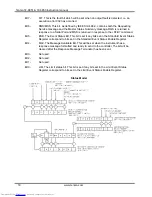
These two registers are implemented as an addition to the IEEE std.488.2. Their purpose is to
allow the controller to be informed of entry to and/or exist from current limit by any output.
Any bits set in the Limit Event Status Register which correspond to bits set in the Limit Event
Status Enable Register will cause the LIM bit to be set in the Status Byte Register.
The Limit Event Status Register is read and cleared by the LSR? command. The Limit Event
Status Enable register is set by the LSE<nrf> command and read by the LSE? command.
Bit 7 ... Bit 3 are not used.
Bit 2 - Set when an output trip has occurred.
Bit 1 - Set when output enters voltage limit.
Bit 0 -
Set when output enters current limit.
Status Byte Register and Service Request Enable Register
These two registers are implemented as required by the IEEE std. 488.2.
Any bits set in the Status Byte Register which correspond to bits set in the Service Request
Enable Register will cause the RQS/MSS bit to be set in the Status Byte Register, thus
generating a Service Request on the bus.
The Status Byte Register is read either by the
∗
STB? command, which will return MSS in bit 6, or
by a Serial Poll which will return RQS in bit 6. The Service Request Enable register is set by the
∗
SRE <nrf> command and read by the
∗
SRE? command.
www.tenma.com
17
electronic components distributor


