ISDN Line Simulator User’s Manual
40-400-00012, Rev. E
24
CHAPTER 5:
REFERENCE
Status Indications
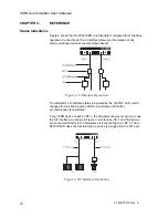
Figure 2 shows the ILS-2000 ISDN Line Simulator configured for U Interface
operation. Connecting to the U Interface allows synchronization of any
communications devices connected downstream.
Figure 2. U Interface Operation
The Simulator’s U interface status is signaled by the U-SYNC LED, which
changes from a blinking green LED to a solid green LED after
synchronization is completed.
If your ISDN device needs an NT-1, the Simulator allows your device to use
the S/T Interface, as shown in Figure 3. In this case, TE-1 and TA devices
are connected directly to the Simulator, as if connecting to an NT-1. The U-
SYNCH LED does not function when a device is plugged into the S/T port.
Figure 3. S/T Interface Operation
Содержание ILS-C
Страница 1: ...ISDN Line Simulator ILS C User s Manual 40 400 00012 Rev E ...
Страница 8: ......

