


SP-401 User Manual
Telpar, Inc.
Page 9 of 25
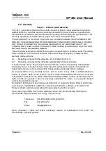
4 Interface Specifications
4.1 Serial Interface
The interface connector is located on the rear of the SP-401 printers.
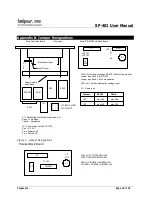
Connector P1 is the serial port. Pin assignments are shown below. See Appendix
B for details.
Note: A valid baud rate must be set at all times for proper printer operation.
See section 4.1.1 for switch settings.
The SP-401 has two types of serial interfaces, RS-232 and 20 mA current
loop RS-485 & 20mA current loop. In general, the RS-232 interface is preferable if
the printer is located close to the host computer and can be connected with a
cable run of 50 feet or less.
RS-232/20 mA Interface
Pin
Signal
Description
1
GROUND
Protective ground
2
TXD
Data output from the printer to the host
3
RXD
RS-232 data input, or 20mA positive input
5
CTS
Inhibits TXD line when held at -10v by the host
7
GROUND
Signal ground
11
BUSY
-10v when printer is unable to receive data
20
DTR
+10v when printer is on line
22
RET
-20mA current loop return
RS-485/20 mA Interface
Pin
Signal
Description
1
DTR -
2
DTR +
3
20 mA
positive input
7
TXD -
8
TXD +
10
GND
19
RD -
20
RD +
22
20Ma
RETURN
20 Ma current loop RETURN


