SP-401 User Manual
Telpar, Inc.
Page 19 of 25
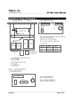
Appendix B. Jumper Designations
Main Controller Board
(Top view)
Serial RS-232/20mA Back Board
Figure 3 - Jumper Designations
Parallel Back Board
Mechanism Input
Optical Sensor
Paper Spindle
and Guides
P1
EPROM
RAM
Z80
8255
P1
1
2
SW 1
1
2
JP6
F1
=
2A
C1
JP3 123
JP2 123
U1
232
SW1
JP1
3
1
4
2
JP1 BACK VIEW
PIN LAYOUT
JP2,JP3=Jumpers to change RS-232 to 20ma loop interface.
Jumper pins 1 and 2 for RS-232.
Jumper pins 2 and 3 for 20ma operation.
JP6 = Auto Time and date after carriage return
F1 = 2 amp fuse
Jumper
RS232
20mA
JP3
pins 1&2
pins 2&3
JP2
pins 1&2
pins 2&3
P1 = Data Mode/Text Mode (see section 5.4)
Open = Text Mode
Closed = Data Mode
JP1 = Power input 8 to 30 VAC/DC
Pins 1 & 2 AC
Pin 3, Negative DC
Pin 4, Positive DC
P1
1 2
JP4
X1
F1 = 2A
74LS373
C1
JP4 = AUTO TIME AND DATE
AFTER CARRIAGE RETURN
OPEN = DISABLE (JUMPER OFF)
CLOSED = ENABLE (JUMPER ON)


