


SP-401 User Manual
Telpar, Inc.
Page 11 of 25
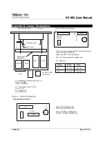
4.2 Parallel Interface
A DB 25S connector (P1) is used for the parallel interface. The pin
assignments and brief signal descriptions are listed below.
Pin
Signal
Description
1
STROBE
1 usec. Pulse to clock data into the
printer
2
DATA 0
3
DATA 1
4
DATA 2
Eight data bit input signals to the printer;
5
DATA 3
Signal levels are high for logic 1 and low
6
DATA 4
for a logic 0.
7
DATA 5
8
DATA 6
9
DATA 7
10
ACK
6 usec pulse from printer when data
received
11
BUSY
High when printer is unable to receive
data
12
PE
Always low. There is no PAPER ERROR
signal supplied at the parallel interface
13
SELECT
High when printer is on line
18-24
GROUND
Signal Grounds
4.3 Flow Control
The SP-401 printers employ a 7K byte data buffer as a standard feature to
allow the host computer to rapidly transfer data. Under some circumstances it
may be possible to completely fill the 7K buffer. When the buffer is within 50
bytes of being full, the SP-401 printers signal the host computer to pause until a
line of data is printed, or until the buffer is under the 50 byte limit. The flow control
information is sent to the host using hardware and software protocols.
The hardware protocol uses the BUSY line of the parallel interface or the
BUSY line of the serial interface. These pins are asserted or negated as
necessary to turn off and turn on the flow of data. The software protocol (Serial
interface only) uses the XON and XOFF ASCII characters (^Q and ^S) which are
sent back to the host to start and stop the data stream. Some host systems may
not support one or both of these protocols.


