background image

USER GUIDE

USER GUIDE

INTEGRATED HUMAN BODY TEMPERATURE SCREENING SYSTEM

V

IR

ALERT 

3

07

3) 

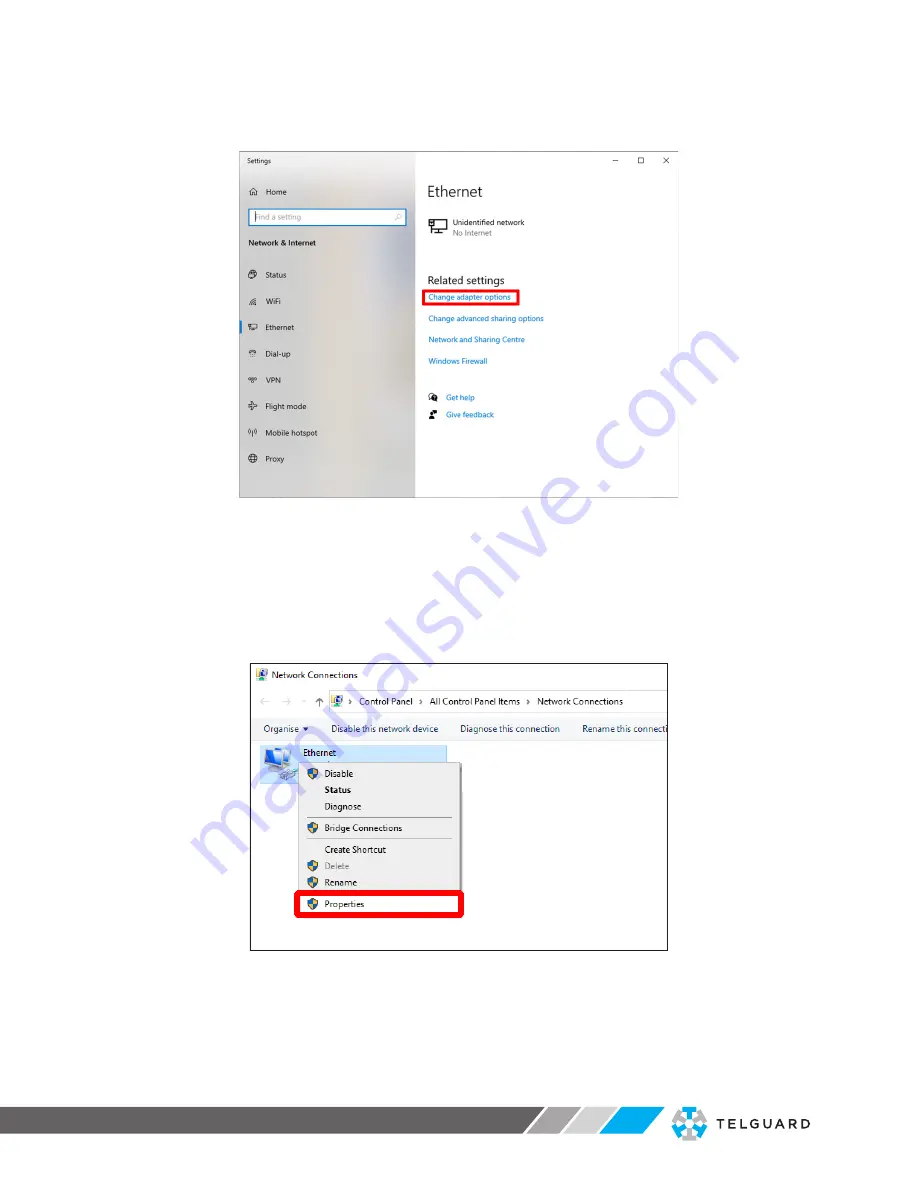
Click on the 

Change adapter options

 link. (See Fig. 4-2)

Fig. 4-2  Status screen

 The 

Network Connections

 screen is displayed. See Fig. 4-3 below.

4) 

Move your mouse cursor over the icon for your Network (Ethernet in the 

example below).

5) 

Right-click with the mouse, and select the 

Properties

 option.

Fig. 4-3  Network Connections screen


Содержание VIRALERT 3

Страница 1: ...INTEGRATED HUMAN BODY TEMPERATURE SCREENING SYSTEM SAFE EASY ACCURATE F R O M T E LG UA R D A N D A M E T E K L A N D THE LATEST TECHNOLOGY AVAILABLE AT LEADING SECURITY INDUSTRY DISTRIBUTORS IN THE U S AND CANADA ...

Страница 2: ... hazardous situation which if not avoided could result in minor or moderate injury to the user or users or result in damage to the product or to property NOTE Indicates a potentially hazardous situation which if not avoided could result in damage or loss of data Signs and Symbols used on equipment and Documentation Caution risk of electric shock Caution attention to possibility of risk of damage t...

Страница 3: ...during transit You must include a written report of the problem together with your own name and contact information address telephone number email address etc Design and Manufacturing Standards The Quality Management System of Land Instruments International is approved to BS EN ISO 9001 for the design manufacture and on site servicing of combustion environmental monitoring and non contact temperat...

Страница 4: ...view 03 3 System Setup 04 3 1 Measurement Location 04 3 2 System Connections 04 4 Start the Software 06 4 1 Network Adapter Settings 06 4 2 Starting the Software 09 5 Software Settings 12 5 1 Accessing the Settings menu 12 5 2 System Settings 13 5 3 Camera Settings 20 5 4 Communication 22 5 5 Changing the Password 24 6 Specifications 25 6 1 System Specifications 25 6 2 Dimensional information 26 D...

Страница 5: ... of the image containing the subject s face VIRALERT 3 uses an infrared thermal imager to determine the highest temperature in the subject s face VIRALERT 3 is a screening tool It has not been cleared or approved by the FDA or any other regulatory agency It should not be relied on solely or primarily to diagnose or exclude a diagnosis of COVID 19 or any other disease 1 2 What s in the box VIRALERT...

Страница 6: ...t Part Number 814266 An adjustable mounting bracket that can be screwed to a wall ceiling or any other flat surface Connecting hardware included Clamp Desk Mount Part Number 814267 A mounting bracket with a clamp to connect to a desk or a table Tripod Part Number 814268 A tripod for installation on a flat surface 02 ...

Страница 7: ...LERT 3 Fig 2 1 VIRALERT 3 Typical System Overview VIRALERT 3 Camera and Blackbody Reference Source Laptop PC running VIRALERT 3 Software requires Windows 10 Measurement Subject Camera Cable Clamp Mount Bracket Power Cable 2 SYSTEM OVERVIEW 2 SYSTEM OVERVIEW 3ft 1m 03 ...

Страница 8: ...stancing in your chosen measurement location 7 The camera must have a clear unobstructed view of the Subject s face ideally with the camera at a height around eye level If necessary use one of the mounting accessories available from Telguard see Section 1 3 8 The Blackbody Reference Source requires a power supply You will also need to provide power to the Laptop PC running the VIRALERT 3 software ...

Страница 9: ...n the cable looks like this Connect it to a USB socket on the laptop which looks like this The Network signal connector on the cable looks like this Connect it to a Network socket on the laptop which looks like this Blackbody Reference Source Connection Connect the smaller connector of the source power cable to the USB port on the Blackbody Reference Source Use the supplied AC adapter to connect t...

Страница 10: ...can communicate with the VIRALERT 3 Camera 1 In the bottom left corner of your PC screen there is a Windows icon Click on the icon so that it turns blue The Windows Start menu is displayed 2 In this text box type in Ethernet Settings The Ethernet Settings screen will be similar to the screen shown in Fig 4 1 below Fig 4 1 Typical Ethernet settings screen 4 START THE SOFTWARE ...

Страница 11: ...adapter options link See Fig 4 2 Fig 4 2 Status screen The Network Connections screen is displayed See Fig 4 3 below 4 Move your mouse cursor over the icon for your Network Ethernet in the example below 5 Right click with the mouse and select the Properties option Fig 4 3 Network Connections screen ...

Страница 12: ...rotocol Version 4 TCP IPv4 Properties screen is displayed See Fig 4 5 below Fig 4 5 Internet Protocol Version 4 TCP IPv4 Properties screen 7 Click the small round radio button next to Use the following IP address to select this option 8 In the text boxes enter the following values IP address 192 168 10 100 Subnet mask 255 255 0 0 9 Click on OK to save these settings 10 Close the Networking Propert...

Страница 13: ...the VIRALERT 3 icon The software will start automatically in Measurement mode 2 Wait for the LED on the front panel of the Blackbody Reference Source to turn green WARNING The warm up rate of the Blackbody Reference Source is 23 F 13 C per minute Therefore from an ambient temperature of 77 F 25 C it will take approximately 1 minute for the source to reach the factory default value of 100 4 F 38 C ...

Страница 14: ...re indicated by a green screen as shown in Fig 4 6 Fig 4 6 VIRALERT 3 Software Normal Body Temperature display Subjects with a high body temperature are indicated by a red screen as shown in Fig 4 7 Fig 4 7 VIRALERT 3 Software Elevated Body Temperature display Reference Area Measurement Area Blackbody Reference Source Measurement Area Reference Area Blackbody Reference Source ...

Страница 15: ...our Blackbody Reference Source moves out of position you will need to adjust its mounting so that it is aligned correctly 5 Access to the Settings menu in which you can adjust the temperature alarm value and units of measurement is password protected The default factory set password is 0000 WARNING The threshold for an elevated body temperature alarm is a critical parameter for use of VIRALERT 3 Y...

Страница 16: ...for 5 minutes or until you press the padlock button again 2 Click on the link in the top left corner of the screen See Fig 5 1 Fig 5 1 VIRALERT 3 Settings Menu location If the menu is not visible this is due to the software being in Full Screen Mode 2 To exit Full Screen mode click on this button in the top right hand corner of the screen The Settings menu option will now be displayed The menus wi...

Страница 17: ...ttings To access the System Settings screen select the System option from the Settings menu The System Settings screen contains four Tabs These are General Alarm Workflow Logging 5 2 1 General System Settings The General tab is shown in Fig 5 2 Fig 5 2 System Settings General options 13 ...

Страница 18: ...is option you will need a Brother QL 700 Label Printer See Label Printing below This option allows you to print a label for each person who is screened by VIRALERT 3 and whose temperature is below the alarm level The label can be attached to the person as an aid to confirming that he or she has been screened by the VIRALERT 3 The label shows the date and time of the measurement Include image on la...

Страница 19: ...ink The Brother QL 700 Properties window is displayed as shown in Fig 5 3 Fig 5 3 Typical Brother QL 700 Properties window 6 Go to the Device Settings tab select Utility and then click on the Properties button The Brother QL 700 Utility window is displayed as shown in Fig 5 4 Fig 5 4 Typical Brother QL 700 Utility window 7 In the Auto power off time setting area change the Time field to 0 and clic...

Страница 20: ... available in the Alarms tab are explained in the table below Option Description Alarm Temperature Use this text input to enter the temperature at which you want the system to indicate an alarm The default value is 100 4 F or 38 C Temperature Trend This section of the screen displays a graphical representation of ten most recent temperature readings plotted against the time of the reading You can ...

Страница 21: ...mera Processing This is when a person s face has been detected and their temperature is being measured Pass This is when a person s temperature has been measured and is below the alarm level set in your system Alarm This is when a person s temperature has been measured and is above the alarm level set in your system You can add text to the message that is displayed for each of the four stages in t...

Страница 22: ...ng images is useful for identifying which person triggered an alarm and logging data is useful for recording temperature value trends Fig 5 7 System Settings Logging options The options available in the Logging tab are explained in the table below Option Description Log Storage Folder This is the folder on your computer network where the logged images and data will be stored A default folder is se...

Страница 23: ...camera Data Logging No data logging No data is saved by the system Log data when a person is detected This option logs data each time a person is detected in front of the camera irrespective of their temperature reading This option will take up the most storage space on your computer system Log data when alarm is triggered This option logs data each time a person with a temperature reading above t...

Страница 24: ...ect this option if the image appears upside down in the camera Show thermal image Select this option if you want to display a small thermal image of the person being measured inset into the visual camera image Areas in the thermal image above the alarm temperature will be shown in red Image position Use this drop down list to select the area of the visual camera image in which you want the thermal...

Страница 25: ...a You should only change the IP Address if you have knowledge of how IP Addresses work and your system installation requires the IP Address to be in a certain format The IP Address tab is shown in Fig 5 9 Fig 5 9 Camera Settings IP Address If you need to change the IP Address and or Subnet Mask enter the required details in the appropriate fields and press OK to confirm the changes 21 ...

Страница 26: ... by VIRALERT are listed below MOXA ioLogik E1214 6 relay outputs MOXA ioLogik E1241 4 analog outputs 0 to 10 V or 4 to 20 mA via software configuration EL4014 4 analog outputs 0 to 20 mA or 4 to 20 mA via software configuration EL2624 4 relay outputs A total of 16 modules comprising any combination of the above modules can be added For more information on the MOXA ioLogik modules refer to the user...

Страница 27: ... the list Multiple modules can be selected for removal 5 If a module you require is not listed you can use the Add New button to enter the details of the required module 6 When you have listed all the required modules click on OK The IO Modules screen now displays a list of the modules connected 5 4 3 Pairs IO Module Data Pairing When you have configured your Modules you can then assign a data sou...

Страница 28: ...uts Outputs is expanded to show the corresponding available Digital Outputs that can be paired to the highlighted data source 3 Click on the required output to highlight it e g E1214 1 D0 0 The details of the New Pairing will be displayed 4 Check that this pairing is correct then press the Add Pair button The new pairing is added to the Existing Pairings list 5 When you have configured the pairing...

Страница 29: ...ng System weight 1 65lb 0 75kg without cables System dimensions inches System 14 x 4 4 x 3 6 BBS 2 6 x 2 4 x 1 4 Camera 4 x 3 2 x 1 8 System dimensions mm System 350 x 110 x 90 BBS 65 x 60 x 35 Camera 100 x 80 x 45 Imager Interface Wired Ethernet Local PC Power supply requirement interfaces 5 VDC USB Local PC Operating Temperature range 50 to 122 F 10 to 50 C Imager Thermal Measurement range 86 to...

Страница 30: ...d audible alarm status Simple traffic light display Automatic face detection Customizable prompts alarms and messaging tailored to user workflow Body mode enabling calculated core temperature from measured skin temperature Operating system Windows 10 Recommended minimum PC specification i3 processor or equivalent 4 GB RAM 1 x RJ45 port and 1 x USB A port 64 GB Hard disk Languages supported English...

Страница 31: ...ems that must be operated strictly in accordance with the manufacturer s operating manual VIRALERT systems are not intended nor designed to diagnose or detect medical conditions including but not limited to viruses or other illnesses Telguard AMETEK Land thermal imaging products should only be used to detect variations of surface temperature If elevated skin temperature is detected the finding sho...

Страница 32: ...ake it necessary to change these details without notice 800 229 2326 3225 Cumberland Blvd SE Suite 300 Atlanta GA 30339 USA telguard com 2020 Telguard Telguard and the Telguard Logo are registered trademarks of Telular Corporation Telular and Land are business units of AMETEK Inc All Rights Reserved 092020RevC ...

Отзывы: