background image

27

CHAPTER 3

Operation

Power-Up Check

When power is first applied to the US-2002, it performs a power-up reset, in which the front panel indicators cycles through all 
of the possible colors and then turn off. This verifies the general operation of the intercom station and indicators. The US-2002 
also reads the settings of all DIP switches at this time and configures itself accordingly.

To 

perform a power-up check

, do the following:

1.

Plug in any 

PA-KP local power supplies

 being used.

2.

Turn on any 

system power supplies

 being used. 

Test Tone

The US-2002 can generate a test tone, which is used to verify intercom channel operation after installation or to locate a 
malfunction. This test tone is also used for the sidetone adjustment, see “Sidetone Adjustment” on page 28.

To 

use the test tone

, do the following:

1.

Simultaneously press the 

All Talk 

and 

PA 

keys to activate the test tone.

2.

Tap the 

Call 

key for the channel you want to test (can be either US-2002 channel or an ES-4000A channel). 

3.

Verify the

 test tone 

can be heard at all intercom stations on the channel. 

4.

Replace any 

defective cables 

or

 intercom stations

 where the test tone is being lost.

5.

Tap the same

 Call 

key


to stop the test signal on that channel.

6.

Press 

any key

, except a Call key, to turn off the test tone.

Содержание Audiocom US-2002

Страница 1: ...US2002 Listen Listen Call Talk Talk Call Mic Kill Volum e All Talk PA Headset Panel Mic Mic User Instructions US 2002 Intercom User Station 9350 7748 000 Rev C 09 2009 ...

Страница 2: ...e made via UPS Ground prepaid you may request from Factory Service a different shipment method Any shipment upgrades will be paid by the customer The equipment should be shipped in the original packing carton If the original carton is not available use any suitable container that is rigid and of adequate size If a substitute container is used the equipment should be wrapped in paper and surrounded...

Страница 3: ...nnections 13 CENTRAL MASTER STATION VS REMOTE STATION 13 ALL LOCALLY POWERED STATIONS 13 EXTERNAL PROGRAM INPUT AND PA OUTPUT 13 ES 4000A EXPANSION STATION CONNECTION OPTIONAL COMPONENT 13 Cables 13 OPERATION 27 Power Up Check 27 Test Tone 27 Sidetone Adjustment 28 Voice Activated Microphone Setup 29 Operation 29 NORMAL VS PROGRAMMING MODE 29 VOLUME ADJUSTMENT 29 RECEIVING CALLS 30 CALLING AN INTE...

Страница 4: ......

Страница 5: ...nels It can be rack mounted or used as a desktop station For rack mounting optional hardware is required For desktop use the four rubber feet supplied The US 2002 can be used as a simple multi channel user station Typically in this application no program sources or public address output are connected and some advanced features can be disabled the station simply provides talk listen and call capabi...

Страница 6: ...4 Features FIGURE 1 US 2002 Reference View See Reference Descriptions on page 5 ...

Страница 7: ...Kill Key Used to turn off the microphones on any intercom station on a channel Also used to activate the program inputs and the audible beep feature 9 Intercom Talk Keys Allows momentary or latching hands free operation possible 10 Call Keys Used to place calls on intercom channels and to indicate calls 11 Intercom Listen Keys Allows momentary or latching operation possible 12 Program Inputs Conne...

Страница 8: ...6 ...

Страница 9: ...one 1 screw from the top cover 2 Remove three 3 screws from each side NOTE Switch SW2 can be accessed through the back panel If you change any switch settings while the US 2002 is operating you must perform a reset either cycle power off then on or simultaneously press the All Talk and Listen 1 keys then release them The sidetone controls are adjusted after power up and are normally accessed throu...

Страница 10: ...Off Disabled On SW1 4 Call signal send channel 2 On Enabled Off Disabled On SW1 5 Call signal receive channel 2 On Enabled Off Disabled On SW1 6 Mic Kill signal send On Enabled Off Disabled Off SW1 7 Program 2 interrupt On Interrupt during talk Off No Interrupt Off SW1 8 Program 1 interrupt On Interrupt during talk Off No Interrupt Off Push button Switch SW2 BAL UNBAL switch on Back Panel Audiocom...

Страница 11: ...ature is useful for example when an unattended microphone has been left on and is causing unnecessary noise on a channel By default Mic Kill is not enabled To activate this feature do the following Set SW1 6 to the on position SW3 2 Listen 1 to speaker 1 only On Enabled Binaural Off Disabled Monaural On SW3 3 Incoming call beep speaker 1 On Enabled SW3 1 must be off Off Disabled Off SW3 4 Incoming...

Страница 12: ... beep in a headset set SW3 1 to off 3 For an incoming call beep in speaker 1 set SW3 1 to off and SW3 3 to on 4 For an incoming call beep in speaker 2 set SW3 1 to off and SW3 4 to on NOTE The procedure for turn incoming call beep on or off during operation can be found on page 32 Monaural or Binaural Operation DIP Switches The US 2002 can be used with a single speaker or monaural headphones singl...

Страница 13: ...om channels can be turned on or off via the US 2002 front panel programming See External Program Input and PA Output on page 13 Additionally all program signals can be routed directly to the US 2002 speaker or headset This lets the US 2002 operator hear the program inputs even if they are not being routed to the intercom channels To disable direct program listening in the speaker or headset for on...

Страница 14: ... NOTE You will have to perform the sidetone adjustment See Sidetone Adjustment on page 28 after all components are connected However when the US 2002 is rack mounted you may not be able to access the sidetone trimmers In this case you can position the US 2002 in the rack and make all required connections Then adjust the sidetone trimmers before installing and tightening all rack mount screws FIGUR...

Страница 15: ...ed connection information Cables The numbers below correspond to the cable number in the connection drawings on the following pages 1 1 channel intercom cable Sold separately Use Bosch ME cables below Or build per Figure 15 on page 26 ME 25 25 7 6 m cable with Male and Female 3 pin XLR connectors ME 50 50 15 2 m cable with Male and Female 3 pin XLR connectors ME 100 100 30 4 m cable with Male and ...

Страница 16: ... follows Pin 1 common Pin 2 program input Pin 3 program input 10 Shielded audio cable Must have male 3 pin XLR connector at one end for connection to the XP USPG PA output Pin out for PA output is as follows Pin 1 common Pin 2 PA output Pin 3 PA output 11 18 457 mm channel output cable 15 pin Male Dsub to 15 pin Female Dsub One 1 supplied with each XP ES4000 REFERENCE For more information see ES 4...

Страница 17: ...er output for the US 2002 and the US 2002 dip switches are set to monaural operation so that both intercom channels are heard in the speaker The PA KP local power supply is optional When a PA KP is connected the US 2002 automatically disconnects from system power supplied by the SPS2001 When the US 2002 is not drawing power from the intercom system more system power is available for additional bel...

Страница 18: ...e completely separated The amplified speaker in the SPS2001 is used as the speaker output for channel 1 and the SPK2000 is used for channel 2 The PA KP local power supply is optional When a PA KP is connected the US 2002 automatically disconnects from system power supplied by the SPS2001 Since the US 2002 is not drawing power from the intercom system more system power is available for additional b...

Страница 19: ...ural operation default setting so both intercom channels are heard in the monaural headphones binaural headphone operation is not supported The PA KP local power supply is optional When a PA KP is connected the US 2002 automatically disconnects from system power supplied by the PS2001L Since the US 2002 is not drawing power from the intercom system more system power is available for additional bel...

Страница 20: ...l 2 The amplified speaker in the SPS 2001 is used as the speaker output for the US 2002 and the US 2002 dip switches are set for monaural operation default setting so that both intercom channels are heard in the speaker The PA KP local power supply is optional When a PA KP is connected the US 2002 automatically disconnects from system power Since the US 2002 is not drawing power from the intercom ...

Страница 21: ...ther SPS2001 are combined on channel 2 The amplified speaker in each SPS2001 monitors a single intercom channel and the US 2002 dip switches are set to binaural operation see page 10 The PA KP local power supply is optional When a PA KP is connected the US 2002 automatically disconnects from system power Since the US 2002 is not drawing power from the intercom system more system power is available...

Страница 22: ...he front panel of the US 2002 and the US 2002 dip switches are set to monaural operation default setting so that both intercom channels are heard in the monaural headphones binaural headphone operation is not supported The PA KP local power supply is optional When a PA KP is connected the US 2002 automatically disconnects from system power Since the US 2002 is not drawing power from the intercom s...

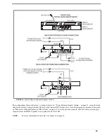
Страница 23: ...ercom station When a PA KP is connected to the US 2002 the US 2002 automatically disconnects from system power This allows more system power for belt packs and other intercom stations Also when the US 2002 is powered by a PA KP it can be operated over a greater distance as a remote station FIGURE 10 Typical Remote Headset Station NOTE For further information about cables see Figure 15 on page 26 ...

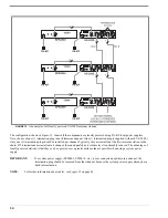
Страница 24: ...on DIP Switches on page 10 A PA KP local power supply is required for the SPK 2000 but is optional for the US 2002 When a PA KP is connected to the US 2002 the US 2002 automatically disconnects from system power This allows more system power for belt packs and other intercom stations Also when the US 2002 is powered by a PA KP it can be operated over a greater distance as a remote station FIGURE 1...

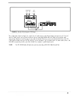
Страница 25: ...the internal DIP switches are set for binaural speaker operation as described on Monaural or Binaural Operation DIP Switches on page 10 As in the previous example a PA KP local power supply is required for each SPK2000 speaker but is optional for the US 2002 NOTE For more information about cables see Figure 15 on page 26 FIGURE 12 Typical Remote Binaural Speaker Station ...

Страница 26: ... are installed in a channel the sound quality and volume level is noticeably reduced The advantage of locally powered stations is that they can be operated over a greater distance than is possible when using a system power supply IMPORTANT If a system power supply SPS2001 PS2001L etc is ever connected anywhere in a channel the termination plug should be removed from that channel because the system...

Страница 27: ... specifications located on page 13 for connector pin out However a more convenient method is to use an XP USPG Breakout Panel as shown The XP USPG lets you use standard 3 pin XLR audio cables to connect audio sources The XP USPG also interfaces the PA jack of the US 2002 to a standard 3 pin XLR audio cable NOTE The XP USPG Breakout Panel can be rack mounted using a BOP 1000 Rack Mount Plate FIGURE...

Страница 28: ...26 FIGURE 15 Audiocom Intercom Cables ...

Страница 29: ... Tone The US 2002 can generate a test tone which is used to verify intercom channel operation after installation or to locate a malfunction This test tone is also used for the sidetone adjustment see Sidetone Adjustment on page 28 To use the test tone do the following 1 Simultaneously press the All Talk and PA keys to activate the test tone 2 Tap the Call key for the channel you want to test can b...

Страница 30: ... send the test tone on channel 1 3 If you are using a headset adjust the volume control at the US 2002 until you hear the test tone OR If you are using a speaker adjust the volume control at the speaker 4 Using a small flathead screwdriver adjust the channel 1 sidetone through the access hole in the bottom of the US 2002 Figure 16 on page 28 to minimize the tone volume 5 Tap the channel 1 call key...

Страница 31: ...ing a headset make sure that breathing and movement do not cause the panel mic indicator to blinks green If they do adjust the vox control slightly more in the counter clockwise direction to eliminate this 6 Speak into the microphone in a normal voice to verify the headset indicator immediately turns green when you talk If it does not move the microphone closer to your mouth NOTE If you are unable...

Страница 32: ...or that channel automatically turns on in preparation to receive a verbal response 2 Release the Call key when you hear a response 3 If you are using manual microphone activation verify the microphone is on For a dynamic mic headset tap the headset key to turn it on For a panel mounted microphone or electret headset tap the panel mic key to turn it on 4 Turn on the Talk key for the channel you cal...

Страница 33: ...alk key to turn the program input for that channel on or off NOTE The current status of the program inputs is indicated by the talk keys If the channel 1 talk key is lit the program 1 input is currently activated to channel 1 if channel 2 talk is lit program 2 is activated to channel 2 5 When the program inputs are configured as desired tap the Mic Kill key to exit programming mode and return to n...

Страница 34: ...is off and blinks or turns green when the microphone turns on NOTE The VOX level may require adjustment see Figure Voice Activated Microphone Setup on page 29 Incoming Call Beep On Off Normally incoming calls are indicated by red flashing call keys To turn the incoming call beep on and off do the following 1 Verify call beep has been activated via internal switches 2 Press and hold the Mic Kill ke...

Страница 35: ...S maximum Input Impedance 75k Ohm Common Mode Rejection Greater than 50dB Connector Type DB9F Pin 1 Ground Pin 2 Program 1 input low Pin 3 Program 2 input low Pin 4 NC Pin 5 NC Pin 6 Program 1 input high Pin 7 Program 2 input high Pin 8 NC Pin 9 NC Intercom Channels Balanced Mode SW2 set to BAL position Output Level 1 VRMS nominal Input Impedance 300 Ohms Bridging Impedance greater than 10 000 Ohm...

Страница 36: ...ne jack Tip Talk output Ring Listen input Sleeve Common External Power Type 2 0mm power jack Internal pin positive External shell negative Headphone Amplifier Voltage Gain 30 3dB Maximum Output 250 mW 10 into 150 Ohms 65mW 10 into 600 Ohms Frequency Response 200Hz to 8kHz 1 3dB Incoming Call Beep Tone 2kHz at the headphones Total Harmonic Distortion Less than 0 2 at 200mW Sidetone 18 2dB adjustabl...

Страница 37: ...l key blinks green and the Talk and Listen keys are green Tap Mic Kill to exit Mic Kill all channels Tap Mic Kill than tap All Talk Mic Kill key blinks green and all Talk and Listen keys are green Tap Mic Kill to exit Program on Hold Mic Kill then tap channel s Talk key key is green Tap Mic Kill to exit Program off Hold Mic Kill then tap channel s Talk key Tap Mic Kill to exit Audible call alert o...

Страница 38: ......
Отзывы: