CC-10
INSTRUMENT MANUAL
Phone:(215) 947-2500 fax:(215) 947-7464 e-mail:[email protected] web site:www.televac.com
CC-10 MANUAL REV D
Page 35 of 40
Y
TELEVA
8.0
I / O Connector
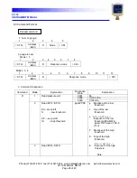
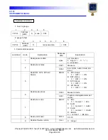
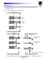
The pin array and the content of the signal of external I / O connector are shown.
1
8
9
15
I/O
Pin number
Cont ent
I/O
Explanat ion
8
+ 24V
Pow er input
+ 24VDC pow er input for CC_10
15
+ 24V COM
+ 24VDC pow er input common
7
EXT Vcc
Signal input
Ext ernal 24V input I/O
14
At mosphere
adjust ment
Trigger input
When it is act ivat ed at mosphere
Adjust ment is t riggered
6
Zero adjust ment
t rigger input
When it is act ivat ed zero adjust ment
is t riggered manually
13
HV inhibit signal
While it is act ivated cold cat hode high
volt age is inhibited and t he gauge is
measured w ith cryst al sensor all t he
t ime
9
ANALOG OUT+
Out put
Analog output
1
ANALOG OUT -
Analog ground
5
SP1
Out put
Set point 1 out
12
SP1 COM
Set point 1 COM
4
SP2
Out put
Set point 2 out put
3
SP3
Set point 3 out put
11
SP2, SP3 COM
SP2, SP3 COM (Common)
10
RS485+
Communicat ion
2
RS485-


