background image


-7- 

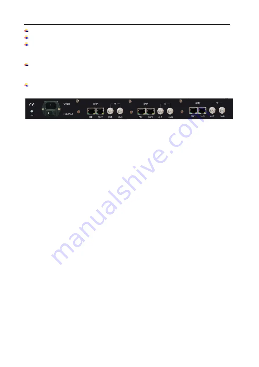
  Power Input Port: To connect to 100~240V 50/60Hz AC input; 

  Power Switch: To turn IDH2-3000 Series on or off; 

  DATA port: two RJ45 GbE connectors, to connect TS IP input from proceeding devices and TS IP 

output  to  succeeding  devices  via  ultra  5  cable  or  category  6  cable;  The  DATA  port  should  be 

connected with L3 switch in the IP head end installation. 

  RF Outputs: RF-OUT port is used to connect IDH2-3000 Series

’ output signal to digital CATV system, 

HFC network or digital terrestrial transmission station via coaxial cables; the RF-20dB port is used 

for monitoring. 

  Grounding  Point:  it  connects  the  device  with  conductive  earth.  Please  make  sure  of  proper 

grounding of the device before start operating it for the safety of the operators and the device itself! 


Fig.2  

Rear Panel View of IDH2-3000 Series 


Содержание IDH2-3000 Series

Страница 1: ...MODEL IDH2 3000 MULTI CHANNEL ...

Страница 2: ...f the device Avoid rapid and frequent power on off or it may cause damages to the semiconductor chipsets Keep proper direction of the power cord when plug into or out from a power socket Connect the grounding pole and signal cable before connecting the power cord Do not touch the power socket with wet hands to avoid electric shocks Take off all jewelry or ornaments such as ring necklaces watches b...

Страница 3: ... 3 2 3 2 MAC address setting 16 3 2 3 3 Parameter setting about system clock 16 3 2 4 Advanced Parameter setting 17 3 2 4 1 Import export reset the parameters 17 3 2 4 2 Back up recover the parameters 19 3 2 4 3 Upgrade back up the software 20 3 2 4 4 Device authorization 21 3 2 4 5 Device control 21 3 2 5 Input output setting 23 3 2 5 1 IP Settings 23 3 2 5 2 Configuration of the Modulation chann...

Страница 4: ... 4 3 3 Front Panel Operation of IDH2 3000 Series 54 Annex A Technical Specifications of IDH2 3000 Series 56 Annex B QAM Reference Information 58 Annex C Frequently Asked Questions 59 ...

Страница 5: ...e CA3 Level 5 4CAS scramble CA4 Table 1 License Type List The product is mainly applied to the DTV network head end room edge of DTV backbone network and DTV branch head end room 1 1 2 2 M Ma ai in n F Fe ea at tu ur re es s This product has the following key features Support ITU T J 83A B C output frequency range 54 MHz 860 MHz Capable of working with 16QAM 32QAM 64QAM 128QAM 256QAM modulation me...

Страница 6: ...el of IDH2 3000 Series The model type and logo information will be displayed on the LCD screen during the device initialization stage User can check some major working status of the device and configure some key parameters of IDH2 3000 Series by exploring the operational menu using buttons and LCD screen after system initialization see section 3 3 for details The POWER LED will be light if the dev...

Страница 7: ...cted with L3 switch in the IP head end installation RF Outputs RF OUT port is used to connect IDH2 3000 Series output signal to digital CATV system HFC network or digital terrestrial transmission station via coaxial cables the RF 20dB port is used for monitoring Grounding Point it connects the device with conductive earth Please make sure of proper grounding of the device before start operating it...

Страница 8: ...into UDP datagram Each output TS should have unique destination IP address unicast or multicast and port number The length of the UDP payload must be 7 188Byte TS packets and the payload must be synchronized by sync byte 0x47 The TS stream except the stream with UDP format also can be output from ASI interface with standard format of 188 byte IDH2 3000 Series may be able to receive multiple transp...

Страница 9: ...0 Series you are currently using and it is in the same subnet with the management workstation you may also start configuring IDH2 3000 Series from the management workstation directly Or otherwise you will need to configure the IP address of management port using front panel control 5 Login to the web browser from the management workstation key in the default user name admin and password 000000 add...

Страница 10: ... 1 1 U Us se er r L Lo og gi in n Entering IDH2 3000 Series IP address in your URL bar after you open the browser then you have the Web management page The device will ask you to input your user name and password to ensure the safety as shown in the figure below Fig 4 User Login There is a factory default administrator user admin in IDH2 3000 Series with password of 000000 Please use this user and...

Страница 11: ...ram scrambling device setting page by clicking different hyperlinks in the area of main menu across the top of this page Remark Device will not auto save your parameters If the device restarts the parameters will change to the state which you saved last time If you have never saved your parameters all the parameters will change to the default state So if you want to save your own parameters please...

Страница 12: ...he home page and then you have the device setting page as shown in the figure below Fig 6 Device setting page Click user management in the select option area on the left side of this page and then you have the user management page as shown in the figure below Fig 7 User management page In this page you could add new user edit old users information or delete an user Remark Only admin user could ent...

Страница 13: ...s but they don t have the right to manage the other user or upgrade the system 3 3 2 2 2 2 2 2 Edit users information In the user information list in this page you can edit an user by clicking the modification button in the same row That makes you edit your password as shown in the figure below Fig 9 Edit users information In this bar you can edit your user s password and that will be accomplished...

Страница 14: ... 2 2 2 2 3 3 Delete an user In the user information list in this page click the delete button in the same row to delete this user Remark You will not permit to delete admin user but can delete the normal user ...

Страница 15: ...g of IP address MAC address set the IP address of time synchronization server open or close this service and set the UTC time synchronization etc 3 3 2 2 3 3 1 1 I IP P S Se et tt ti in ng gs s In the page of figure 11 input a right IP address in the IP settings bar then click submit to set IDH2 3000 Series network parameter Remark To ensure the proper working of device you should guarantee that t...

Страница 16: ...set a right network clock server address IDH2 3000 Series will update his system clock with the period which the user sets if SNTP service and network clock server are enabled Set system clock by manual operation In the page of figure 11 you can set manually the system clock in the date time UTC bar And you can also click get UTC time then click submit button to finish setting Remark 1 If the netw...

Страница 17: ...software import the authorization document restart the device etc 3 3 2 2 4 4 1 1 I Im mp po or rt t E Ex xp po or rt t R Re es se et t t th he e p pa ar ra am me et te er rs s Import the parameters In the page of figure 13 click browse button in the Import Export Reset the parameters bar to choose the parameters document of the device Fig 12 Import export reset the parameters page After choosing ...

Страница 18: ...parameters Remark 1 Please do not turn off the device or pull the power off when the device is importing the parameters 2 The device will restart after importing the parameters 3 Export the parameters In the page of figure 13 click Export button it allows you to save parameter to a file then click Save button to choose the path you wanted to save these parameters Reset the parameters In the page o...

Страница 19: ... Backup button you ll have this dialog box Click YES button system will create a new back up document In the same time input parameter description information will show you the new back up document description as shown in the figure below Remark System could only save a unique back up document each time the new back up document will cover the last one Restore the parameters When the device has a b...

Страница 20: ... you ll have this dialog box Select the upgrade document click Open button as shown below Click Upgrade button system will change the page to uploading management page as shown below Fig 15 Document uploading management page System will checkout the uploading document if its format is right there will appear mark in the uploading bar and document checkout bar Click Submit button you ll have this d...

Страница 21: ...rt the authorization file to upgrade the device As shown in the table 1 IDH2 3000 Series has multiple types of authorization please verify the authorization type before you buy this device After buying this device if you want to get a higher configuration you can also contact with our salesman to buy the authorization For managing the authorization you should give us the authorization applied code...

Страница 22: ... 22 Fig 16 Device reboot information Click YES button to reboot the device ...

Страница 23: ...n below Fig 17 Input Output Setting main page The number and the name of input output channel of the device are listed in the Select Items in the left side of this page as shown below Fig 18 List of the input output channel 3 3 2 2 5 5 1 1 I IP P S Se et tt ti in ng gs s Click Channel01 IP interface hyperlink as shown above the configurable parameter is shown in the channel settings as shown below...

Страница 24: ...rlink the page of the configuration of Modulation channel is shown in channel settings page as shown below Fig 20 Configuration page of Modulation channel Channel parameters Standard of the ITU encoding bandwidth frequency modulation mode symbol rate inversion of spectrum switch of the modulation gain and switch of the RF can be set in this page of the channel settings Range of the parameter setti...

Страница 25: ...is used in China 2 The symbol rate of Annex B in ITU encoding standard is fixed at 5 057MBaud s For Annex A the symbol rate is in the range from 4 200Mbaud s to 7Mbaud s and it s in the range from 4 200Mbaud s to 5 310Mbaud s for Annex C the minimum step size is 1KBaud 3 The bandwidth is defined as 6MHz in Annex B and Annex C 4 If the channel parameters are displayed as grey as shown as the channe...

Страница 26: ...tiplexing setting page of IDH2 3000 Series as shown in figure 21 Fig 21 Multiplexing setting of programs The multiplex parameter configurations are listed in the Select Items in the left side of this page including the module selection general setting manual PID map manual PSI inserter NIT edit input service and output service Fig 22 List of the multiplex parameter configurations ...

Страница 27: ...ter sets setting and transform functions built in IDH2 3000 Series to ensure the received program information over transport stream can be displayed correctly meanwhile ensure this information can be displayed correctly in the next device It can be set in the column of default character sets of input output There are 3 kinds of character sets LATIN GB2312 UTF 8 Remark 1 At present GB2312 is used i...

Страница 28: ... Remark 1 Whether the TDT TOT is actually sending depends on the switch of output service please refer to section 錯誤 找不到參照來源 3 3 2 2 6 6 2 2 P PI ID D m ma ap pp pi in ng g f fu un nc ct ti io on n The system will discard the private PID if it cannot be recognized The needed private PID can be mapped by the PID mapping function and mapped private PID can be passed through and transmitted by the de...

Страница 29: ...utput PID set a PID number from the input PID Switch switch on the selected PID will map to selected channel After the configuration click Submit button at right bottom of the page to save the setting Remark 1 The range of input TS index is from 1 to 250 when the input TS index is out of the boundary the operation will failure 2 The range of input TS index is from 1 to 16 when the output TS index ...

Страница 30: ... io on n i in ns se er rt ti io on n IDH2 3000 Series supports the PSI data update i e OTA file BAT SDT e g The maximum size of the total updated file is 1smaller than the total size and the bandwidth of the updated data is smaller than the total bandwidth 3 3 2 2 6 6 3 3 1 1 A Ad dd d u up pl lo oa ad d f fi il le e As shown in figure 23 click the Manual PSI Inserter hyperlink the PSI information...

Страница 31: ...ad management page as shown below The system will adjust the uploaded PSI file if the file is uploaded correctly and the file layout is correct the column of upload status and file adjust will display this characteristic Click the Submit button below the upload will succeed as shown below ...

Страница 32: ...any column Click the Delete button in the bottom of this page and then click Submit the selected PSI information will be deleted 3 3 2 2 6 6 4 4 N NI IT T e ed di it t The NIT of the transport stream of DTV support the information of the physical layer of the network IDH2 3000 Series supports edit NIT manually As shown in figure 27 click NIT edit button the NIT edit page is shown in the right side...

Страница 33: ...work name NIT version frequency modulation module symbol rate FEC inner coding FEC outer coding While the modulation mode FEC inner coding and FEC outer coding are selected by drop down list the other parameters are manually input After the configuration click Submit button at right bottom of the page to save the setting IDH2 3000 Series supports the edit of NIT Network Descriptor and NIT TS Descr...

Страница 34: ...is page then click Submit the selected NIT network descriptor will delete NIT TS descriptor edit as shown in figure 31 click the corresponding edit button after the NIT information the box of descriptor type display NIT TS descriptor Fig 30 NIT TS descriptor edit The edit of NIT TS descriptor is same as the NIT Network Descriptor the detail please check the specification of the edit of NIT Network...

Страница 35: ...e This button can control the transmission of all the NIT information 3 3 2 2 6 6 5 5 I In np pu ut t S Se er rv vi ic ce e As shown in figure 32 click button which at the left side of the input service hyperlink the input service menu spread up as shown below Fig 31 Input service menu The type of the current input channel is displayed in the input service menu As shown in figure 32 spread channel...

Страница 36: ...Input TS program information 3 3 2 2 6 6 5 5 1 1 P Pr ro og gr ra am m s se ea ar rc ch h As shown in figure 34 click button at the bottom of the page the system will search the corresponding channel automatically and display the information as shown below Fig 34 Input service information 3 3 2 2 6 6 5 5 2 2 P Pr ro og gr ra am m i in nf fo or rm ma at ti io on n c ch he ec ck k ...

Страница 37: ...button at the right side of the program name the details spread up below Fig 36 Program TS information 3 3 2 2 6 6 5 5 3 3 S Si in ng gl le e p pr ro og gr ra am m m mu ul lt ti ip pl le ex xi in ng g When user multiplex the single program the multiplexing output channel of this program can be chose as shown below ...

Страница 38: ...mu ul lt ti ip pl le ex xi in ng g IDH2 3000 Series supports batch program multiplexing It means multiplex all the programs of one channel to another selected channel As shown below Fig 38 Program TS information Open the drop down list box of the output location of the batch select program and select the channel click the Submit button the multiplexing sets successfully as shown below ...

Страница 39: ...r sets detail in 3 2 6 1 1 Switch of deletion after failure when the search failure switch on will delete all the information of current page 3 3 2 2 6 6 6 6 O Ou ut tp pu ut t s se er rv vi ic ce e As shown in figure 40 unfold Output Service to open the output program channel menu shown as below Fig 40 Output Channel Menu Output program channel will list the type of output channel As shown in fig...

Страница 40: ... TS ID PAT version PMT version SDT version CAS output programs etc Pass through users can choose to pass through the input stream by turn on the pass through switch shown as below Fig 43 Pass through Selection Remark In pass through mode the TS is unable to be edited PSI SI Information users can manually configure the PSI SI information of the output TS Configurable parameters includes TS ID PAT v...

Страница 41: ...table information include program name program number PMT information PCR PID EIT information CA related information ES information etc TS information Users can type the program name program number and provider in the corresponding boxes and click Submit button to validate the setting PMT information Users can type the value of PMT PID PMT version sending interval in the corresponding boxes and cl...

Страница 42: ... the Descriptor Type box at the bottom of the page will display Service SDT Descriptors shown as below The way to edit SDT descriptor is the same as the way to edit NIT descriptor see section 3 2 6 4 1 ES information Click button in front of the TS to open the TS information list Users can type the value of ES PID in the corresponding box and turn ON OFF the sending switch To edit ES descriptor cl...

Страница 43: ...ete the program To delete all programs check the Service Remove Mark Select All box at the lower left corner shown as below Fig 46 Delete All Programs All programs service remove mark will be automatically checked then click Submit button to delete all programs ...

Страница 44: ... Setting link in the navigation bar to enter the program scrambling setting page shown as below Fig 47 Scrambling Setting page In Select Items column there are scrambling configuration options including General Setting CAS Configuration and Services Scramble Setting Fig 48 Select Items ...

Страница 45: ...een 10000 60000 milliseconds Click Submit button to validate the setting Fixed CW when it is ON CW will be a user defined fixed value despite the default crypto period Click Submit button to validate the setting 3 3 2 2 7 7 2 2 C CA AS S C Co on nf fi ig gu ur ra at ti io on n 3 3 2 2 7 7 2 2 1 1 C CA A P Pa ar ra am me et te er r S Se et tt ti in ng gs s IDH2 3000 Series support up to 4 CAS simul...

Страница 46: ... generator Remark To ensure IDH2 3000 Series can correctly receive the ECM data from the CAS the value of ECMG IP and ECMG port on the IDH2 3000 Series must be the same as their counterparts on the CAS server Super CAS ID HEX valid range between 0 0xFFFFFFFF Remark 1 The superCASID for different CAS should not be the same 1 SuperCASID for each CAS company must be the legal value which is authorize...

Страница 47: ...2 AC Editing Box As shown in figure 52 users can type AC information s name and content After the editing click Submit button to validate the settings To delete the AC check the square box at the end of the AC information click Remove button and then click Submit button to validate the setting Remark 1 AC information to be added should be provided by the CAS company 2 When editing the AC content i...

Страница 48: ... PMT their CA original CA descriptors will be replaced by new CA descriptor which are generated by IDH2 3000 Series For pass through mode those original CA descriptors will be persisted 2 IDH2 3000 Series supports up to 4 CAS simul crypt The CAS s AC information is available for use only when the CAS is ON 3 For different CAS AC information may have different meanings 4 To correctly scramble progr...

Страница 49: ... bar to enter the monitoring page shown as below Fig 55 Monitoring Page In the monitoring page users can monitor the device temperature and other alarming related information In the Select Items column there are two categories Alarms and Bitrate Monitor shown as below Fig 56 Select Item ...

Страница 50: ...igure 58 left column displays multiple alarm information When there is no alarm the status light will be when there is an alarm the status light will turn to and the counter will start to count the number of errors occurred shown as below The counter will automatically restore to zero even the error is cleared Users need to click the Reset button to reset the counter to zero Remark the status ligh...

Страница 51: ...hown as figure 59 click status button to enter the module status page shown as below Fig 59 Daughter Board Status Page Shown as figure 61 the right column is for the temperature alarm setting including general switch critical temperature and fan active inactive temperature The left column shows the communication status between the current module and the CAS General Switch choose between ON OFF to ...

Страница 52: ...B Bi it t R Ra at te e Unfold the Input Channel menu to enter the input channel bit rate monitoring page shown as below Fig 61 Channel Bit Rate Monitoring Shown as figure 61 the left column displays the real time bit rate of each channel the right column enable users to set the bit rate alarm setting including lower limit upper limit and the enable switch Lower Limit when the real time bit rate is...

Страница 53: ...nd the enable switch Lower Limit when the real time bit rate is lower than this lower limit value it will trigger an alarm Upper Limit when the real time bit rate is higher than this upper limit value it will trigger an alarm Enable Switch turn ON OFF the alarm When finish the settings click Submit button to validate them 3 3 2 2 8 8 2 2 3 3 S Sy ys st te em m B Bi it t R Ra at te e The bottom of ...

Страница 54: ...D display will show the first sub menu of the main menu VIEW ALARMS as shown in the figure below Fig 64 Front Panel Menu When entering operating menu user may switch between different sub menus by pressing LEFT and RIGHT keys The front panel sub menu items of IDH2 3000 Series are shown in the below table Menu ID Function Operating Description Remarks 1 0 Alarms Display the system alarm information...

Страница 55: ...ss Display the MAC address Read only 4 0 Factory reset Execute a factory reset Press ENTER key to enter the selection mode Use and keys to select Select Yes to reboot the device 4 1 Factory Defaults Restore to factory defaults Press ENTER key to enter the selection mode Use and keys to select Press ENTER key to apply changes Select Yes to reboot the device 5 0 Language Set the menu language on fro...

Страница 56: ...erface Connector RJ45 Quantity 2 Data Format TS OVER IP UDP Impedance 75Ω MAC IEEE 802 3 1000BASET Input Data Rate per Port 0 800Mbps Management Port Connector RJ45 Quantity 1 Functionality Management and CAS MAC IEEE 802 3 1000BASET Network Protocol TCP IP Application HTTP4 0 HTML1 1 XML CGI Web Management NTP A 3 Multiplexing Specifications Characteristic Properties Specification TS input Input ...

Страница 57: ... 0 3Mbps TS A 5 RF Output Technical Specifications Characteristic Properties Specification RF Output Output Frequency 54MHz 860MHz Maximum Output EPL main 90 110dBuV 16 channels 0 5dB as step size Maximum Output EPL monitoring 70 90dBuV 16 channels 0 5dB as step size Impedance 75Ω Reflection Loss 12dB Carrier Suppression 58dB MER 38dB QAM Mode 64QAM Symbol Rate 6 857MBaud SNR Out of band 50dB Gain...

Страница 58: ... 2 14 1 15 8 05 1 7 4 28 1 15 8 05 1 7 5 35 1 15 8 05 1 7 6 42 1 15 8 05 1 7 7 49 1 15 8 05 1 7 8 56 1 15 8 05 1 7 Channel Bandwidth 1 15 Symbol Rate Symbol Rate Output Bit Rate m m 2 4 5 6 7 8 Corresponding QPSK 16QAM 32QAM 64QAM 128QAM and 256QAM 8MHz Maximum Output Bit Rate Constellation C N Threshold Maximum Valid Bit Rate Channel Utilization Ratio 16QAM 32QAM 64QAM 128QAM 256QAM 22dB 25dB 28d...

Страница 59: ... cable is properly worked or change the cable Fail to scan programs in specific input Source device is not working properly Check malfunction in the source device Succeeding device fails to receive any program Improper connection of RF output cable Connect the RF output cable properly Low EPL at RF output Re configure output EPL Succeeding device fails to receive data in specific output The succee...

Отзывы: