background image


SeaBat Sonar UI - User Manual 

Appendix Dual head (Master 

– Slave)  

  89 

Step 

Action 

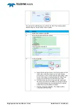
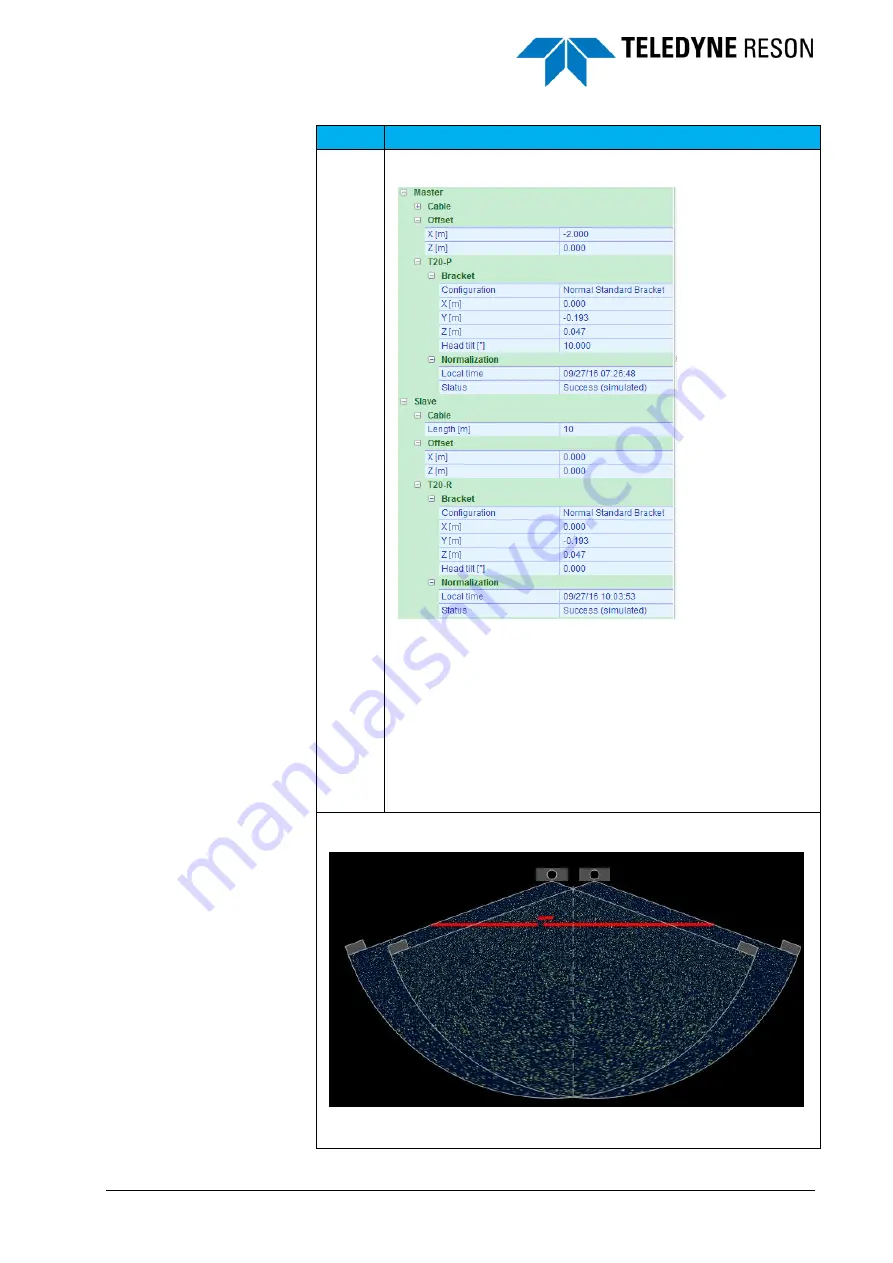
The dual head properties will extend after a successful 
connection with the slave. 


Enter the Master and Slave sonar offset with respect to the 
vessel’s Centre Reference Point (CRP). 
The offsets are from the sonars acoustic center to the CRP of 
the vessel. On the moment of writing it is only for proper 
indication of the wedge and therefore doe

sn’t need to be set 

very accurate. 
 
Enter when applicable the correct head tilt. 
 

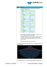
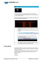
Two wedges appear at the master SUI. One for the Master and one for 
the Slave sonar. 


Hover with the cursor over the head for a Master/Slave indication text 

Содержание UI

Страница 1: ...User Manual SeaBat Sonar UI Version 1 4 7 June 2017 Teledyne RESON B V Stuttgartstraat 42 44 3047 AS Rotterdam The Netherlands Tel 31 0 10 245 15 00 www teledyne reson com ...

Страница 2: ... Guide Text modified Operation Text modified 1 3 2 25 03 2015 Operation AUV text added 1 3 1 26 02 2015 Operation Record text modified Service figures modified 1 3 0 19 02 2015 Manual updated after review 1 2 1 14 01 2015 General information Added text Wake up Operation Text modified leds toolba r 1 2 0 11 12 2014 SeaBat User interface becomes Sonar User interface as different sonar types will use...

Страница 3: ...Bat UI version 4 0 0 4 1 0 3 04 06 2012 Minor updates 1 0 2 24 05 2012 Updated to the latest SeaBat UI version 1 0 1 14 05 2012 New items added to the SeaBat UI User Manual 1 0 0 26 04 2012 First version of the SeaBat UI User Manual ...

Страница 4: ......

Страница 5: ... Settings Dialog 12 3 3 1 1 Lay out 12 3 3 1 2 Sonar System 13 3 3 1 3 Sonar Network Connections 14 3 3 2 About Dialog 15 3 3 3 Licensed Features Dialog 15 3 3 4 Help File 16 3 3 5 Sonar Address 16 3 3 6 Service Mode 16 3 3 7 Operation Mode 16 3 3 8 Save JPG Screen Snapshot 16 3 3 9 Start Record AVI 16 3 3 10 Start Record RDR 17 3 3 11 Start the Tracker 17 3 3 12 Pitch Stabilization 17 3 3 13 Roll...

Страница 6: ...ilter 33 4 3 11 Temperature 34 4 4 Messages 34 4 5 IO Module 35 4 5 1 Sound Velocity 36 4 5 2 Clock 37 4 5 3 Attitude 37 4 5 4 Depth 37 4 5 5 Position 37 4 5 6 Heading 37 4 5 7 Pan and Tilt 37 4 6 Detection 38 4 6 1 Depth Gate 38 4 6 2 Range Gate 40 4 6 3 Adaptive Gate 40 4 6 4 Tracker 41 4 6 4 1 Coverage angle 41 4 6 5 Snippets 41 4 6 6 Multi detect 42 4 6 7 Vernier Parameters 42 4 7 Display 44 4...

Страница 7: ... Parts Creation 61 4 10 3 1 Pipe segment length 61 4 10 3 2 Maximum detection distance 61 4 10 3 3 Maximum number of predictions 61 4 10 3 4 Quality test 62 4 10 3 5 Depth test 62 4 10 3 6 Number of detections test 62 4 10 4 Pipe Route Creation 62 4 10 4 1 Maximum pipe parts used in routing 62 4 10 4 2 Join segments test 62 4 10 5 Pipe Steering 62 4 10 6 Five Points Environment 63 4 10 6 1 Environ...

Страница 8: ...on 93 7 2 Scenarios 93 7 2 1 RDR on a Gx processor 93 7 2 2 RDR on an external customer computer 94 7 2 3 RDR on a Network Attached Storage device 95 7 2 4 T20 RDR on an external computer in a local network E g Workgroup 96 7 2 5 T20 RDR to external computer in a Domain 97 7 2 5 1 Additional notes 97 7 3 Creating a workgroup 98 7 4 Setup correct IP address and Subnet mask 100 7 5 File sharing 102 ...

Страница 9: ...th dialog box 21 Figure 4 2 Sonar UI with four screens 22 Figure 4 3 Main Pane with Control and Tile settings 23 Figure 4 4 Range 23 Figure 4 5 Power 24 Figure 4 6 Gain 24 Figure 4 7 Pulse Length 25 Figure 4 8 Gate modes with Depth gate selected highlighted 25 Figure 4 9 Ping Max Rate 25 Figure 4 10 Tile with Wedge Water Column and snippets screen switched on button highlited but Sidescan screen o...

Страница 10: ...e 4 47 Vernier parameters 42 Figure 4 48 Display pane 44 Figure 4 49 Display pane with Detect and Water Column settings 45 Figure 4 50 Multibeam Data Color Mode 46 Figure 4 51 Recording pane 47 Figure 4 52 Set path for the file 47 Figure 4 53 Record selection 48 Figure 4 54 Compressed Water Column 49 Figure 4 55 Status raw data recording 49 Figure 4 56 Deck mode 50 Figure 4 57 Hardware part for th...

Страница 11: ...94 Helmsman screen with warning distance indication In this example when the distance exceeds 4 meters 75 Figure 5 1 Diagram in the Service of a Sonar SV2 78 Figure 5 2 Module in error red 7KCenter correct green 78 Figure 5 3 Service tabs 79 Figure 5 4 Example of error messages in the Status page 80 Figure 5 5 Example of part of the HTML file 81 Figure 5 6 Example of BITE information on the Detail...

Страница 12: ......

Страница 13: ...SeaBat Sonar UI User Manual Tables i Tables Table 1 Toolbar buttons Wedge Detect Water column screens 65 Table 2 Toolbar buttons Snippets display 66 ...

Страница 14: ......

Страница 15: ...Sonar UI The different panes that can be used in conjunction with the screens are explained in detail see page 21 The last chapter Service discusses how to check the status of the complete sonar system by viewing the system diagram and BITE information see page 77 Appendix Dual head configuration discusses the dual head configuration in more detail see page 87 Appendix Raw Data Recording discusses...

Страница 16: ......

Страница 17: ... features available When the license is not yet installed a valid license file can be dragged and dropped at the 7k Control Center or at the Sonar UI See the Operation Manual of the sonar for more details b It is possible to open the Sonar UI sonar type depended from The 7KcontrolCenter Select in the 7KControlCenter the option New Sonar UI and click on the Start button to open the Sonar UI Figure ...

Страница 18: ...m In the hardware the roll stabilization must enabled and the correct settings selected see page 50 g Check the 1PPS is received and the roll pitch stabilization is working h Open the Main pane to start the sonar see page 23 Set the power and the gain to start the sonar pinging Change the range so the data is properly displayed in the wedge see page 23 i Select the right frequency pulse type and b...

Страница 19: ...nar UI uses tabs on the right side and at the bottom to open the settings panes the control panes and the messages pane of the Sonar UI 3 2 1 Panes The settings panes on the right side are Display Detection Recording Hardware IO Module Pipe The three panes control and messages at the bottom are Main Advanced Messages This section will explain how to open dock drag and hide the panes See the chapte...

Страница 20: ...ide the pane and click to hide the pane again 3 2 1 2 Docking It is also possible to use the context menu of the pane to switch between Auto Hide and Docking modes see page 11 1 Click on the pin at the upper right corner of the pane to keep the pane from auto hiding The pin will change to the pane is now in Docking mode pinned and will stay open even when clicking outside the pane 2 Click on to un...

Страница 21: ...e can easily be docked at the original right side of the display as guide diamonds are visible when the window is dragged See Figure 3 3 The guide diamonds help dock floating panes to their original default location on the display The settings panes are docked on the right side of the display The bottom panes are docked at the bottom of the display Drag the floating window to one of the two guide ...

Страница 22: ...ed at the right side of the display as indicated by a placeholder 3 The settings pane will be placed above an opened bottom pane Figure 3 5 Re dock settings pane placed above bottom pane When dragging a settings pane to the guide diamond on the right side of the display then 1 The settings pane will be placed on the right side of the display 2 An opened bottom pane will be shifted to the left ...

Страница 23: ...m right guide diamond Re docking bottom panes See Figure 3 7 1 Drag the floating bottom pane to the center guide diamond 2 When dropping the pane it will be placed at the bottom of the display as indicated by a placeholder 3 The bottom pane will be shifted to the left when a Settings pane is open ...

Страница 24: ...ide diamond When dragging a bottom pane to the lower guide diamond while a settings pane is opened then 1 The bottom pane will be placed at the bottom of the display 2 The settings pane will be shifted to the top Figure 3 8 Re dock bottom pane from the bottom guidance diamond and an opened settings pane ...

Страница 25: ...ent pane tab is selected this pane will be displayed on this location It is not possible to display more than one settings pane or bottom pane on a location other than the default on the right or at the bottom respectively 3 2 1 5 Context Menu The different modes for the panes are also selectable from a context menu Right click in the pane to open the context menu Figure 3 10 Context menu ...

Страница 26: ...lication settings dialog 3 3 1 1 Lay out Reset When the layout is disturbed select the check box to reset the layout and font size of the Sonar UI Font size It is possible to set the font size to Small Medium and Big This only applies to the font in the panes Color mode With the color mode the light conditions for the screen s are modified for better viewing conditions on an individual basis The f...

Страница 27: ...g fine in the Windows Classic Theme In the Windows 7 Basic and Windows 7 Themes not all the items on the screen will be supported 3 3 1 2 Sonar System Restore factory settings Select this checkbox to restore the factory settings of the sonar This also includes settings for the I O module and network connections IP settings Reset Sonar settings Select this checkbox to reset only the sonar settings ...

Страница 28: ...he processor network port A T series processor PSP LAN1 port has a default setting of 10 11 10 1 and LAN2 a default setting of 10 11 10 2 with subnet mask 255 255 255 0 for both ports Select the Restore factory settings checkbox in the Application Settings dialog box to set the default settings for the ports Automatic IP address Select the automatic IP address checkbox when a DHCP network is avail...

Страница 29: ...e 3 13 About Sonar UI dialog 3 3 3 Licensed Features Dialog Click on to open the dialog Figure 3 14 Licensed Features dialog The Licensed Features dialog displays the licenses of the feature packages as purchased by the user New license files are dragged and dropped at the Sonar UI and installed automatically ...

Страница 30: ...rent colors are Blue When the Sonar UI is started the BITE information is not yet available Green No errors in the BITE information all components are working Red Error level Errors warnings or timeouts in one or more components Check the diagram in the Service for more information see page 78 3 3 7 Operation Mode Click on Operation to open the view with the sonar data See for more information the...

Страница 31: ... Click on the Tracker button to start the Tracker When in tracker mode the button is highlighted The Tracker is a fully automated mode of operation In the Detection pane the tracker parameters can be selected These parameters including swath width are set by the system on the basis of the quality of the collected data Once the Tracker has been selected no further operator input is required When no...

Страница 32: ...ta received roll value exceeds 35 or change rate 10 per second 3 3 14 1PPS The LED indicator will indicate if the 1PPS is received or not Be aware the status of the LED is an indication related to the last received ping This means when the sonar does not ping the status of the LED is not updated The different colors are Blue When the Sonar UI is started the 1PPS is not yet initialized Green The 1P...

Страница 33: ...tomatically pop up The toolbar automatically hides when the cursor is moved away Figure 3 15 Toolbar in one of the views pops up automatically The screen toolbar options are also available in a context menu Right click the screen to open the context menu The toolbar and context menu are used to adjust the screen properties For more details see the chapter Operation on page 21 ...

Страница 34: ......

Страница 35: ... box to specify the transmit cable length Figure 4 1 Cable length dialog box It is essential the correct cable length is specified A wrong cable length can damage the system When the Sonar UI is started it will open in the Operation mode with four screens or the number of screens that were open when the Sonar UI was closed before ...

Страница 36: ...ontrols the sonar and selects what screens to view during operation Messages see page 34 The Messages pane displays the error message as they are received in the Sonar UI Advanced see page 27 In the Advanced pane the operator can set advanced sonar settings IO Module see page 35 In the IO Module the sensor data can be selected and interfaced into the 7K system Detection see page 38 In the Detectio...

Страница 37: ...is explained in chapter Arranging the Panes on page 5 The different screens are Wedge see page 69 Water Column see page 71 Detect see page 72 Sidescan see page 72 Snippets see page 73 Helmsman see page 74 4 2 Main The Main pane is for general control of the sonar The choice of screens Wedge Sidescan Helmsman Water Column Detect and Snippets allows the operator to customize the display layout in Op...

Страница 38: ... the vessel itself 4 2 3 Gain The gain setting allows the operator to select the amount of receiver gain that is applied to the returned sonar signal in addition to the calculated gain The gain is applied throughout the range as a fixed gain value Figure 4 6 Gain The sonar system utilizes a Time Varied Gain TVG by applying a variable gain to the signal based upon the formula Receiver Gain 2 α Rkm ...

Страница 39: ...en enabled the Gate mode button is highlighted Figure 4 8 Gate modes with Depth gate selected highlighted Settings for the different gate modes are set in the Detection pane See page 38 38 4 2 6 Ping Max Rate The max ping rate setting allows the operator to set the number of pings per seconds The actual number of pings depends on the current range setting Figure 4 9 Ping Max Rate The recommended v...

Страница 40: ...Helsman button has three functions switching on the Sidescan screen switching on the Helsman screen or switching both off When a screen is disable no historical data will be logged This means that a screen will start empty if it is enabled during operation The screens can be resized by dragging the horizontal or vertical divider up down or left right To drag the divider move the cursor over the di...

Страница 41: ...recks and vertical structures such as harbor walls Equi Angle should be used in preference to Equi distant see also section Equi distant The default for Equi Angle is the minimum number of beams for 100 ensonification The number of beams can be set by the operator with the slider This allows the operator to be able to capture the highest detail using the highest beam density needed In very shallow...

Страница 42: ...edge of the sector When the custom checkbox is selected the number of beams can be set with the slider Figure 4 15 Custom checkbox ticked to set the number of beams The spacing distance between de beams can be set when additional to the custom checkbox the Constant spacing checkbox is selected When the constant spacing checkbox is enabled the shape of the bottom is followed With the Maintain swath...

Страница 43: ...de bar see below Figure 4 17 Setting the Outside spacing The high density spacing is set by the slides in the wedge This slides become visible in the wedge when the Flexmode is selected Drag the slides and the high density spacing changes 30 Total swath High density sector Low density sector Low density sector Default settings Total swath 90 High density sector 45 centered Altitude 5m DTM density ...

Страница 44: ...ator to steer the swath electronically The achievable steering depends on the selected coverage angle see Coverage angle on page 31 The default button resets the steering to 0 The coverage angle will also reset The extent of the steering is determined by the coverage angle selected The limitation is that the outer beam cannot be steered past 5 from the horizontal When the swath is steered this way...

Страница 45: ...pending on the selected beam mode The horizontal steering will also be reset 4 3 4 Frequency For a dual frequency system the frequency setting allows the operator to switch the frequency on the fly without restarting the 7K Center All sonar controls will then be dedicated to the selected frequency Figure 4 23 Frequency Lower frequency provide a long range functionality and the higher frequency a h...

Страница 46: ...cy of 210kHz will disturb the sonar signal with a pulse type CW at 200kHz while the pulse type FM has no or very little disturbance from the echo sounder 4 3 7 Absorption The absorption slider allows the operator to set the amount of loss that is expected through the ambient water medium The absorption loss is proportional with the salinity of the water and the sound frequency the higher the salin...

Страница 47: ...ct spreading loss value is not known an initial value of 30dB is recommended Figure 4 28 Spreading 4 3 9 Sound Velocity When the override checkbox is checked the sound velocity slider allows the operator to enter a value for speed of sound in the water When a sound velocity sensor is interfaced and the override checkbox is not checked the sound velocity value as displayed will be the value as rece...

Страница 48: ...ure Select the override checkbox to use the temperature as set by the slider Figure 4 31 Temperature 4 4 Messages In the Messages pane the operator can see the error messages related to the sensor interfacing Figure 4 32 Messages All the error messages will be displayed in the Messages list By accepting an error message it will be removed from the list This will not mean that the error is solved b...

Страница 49: ...et in the Advanced Control see page 33 is used instead If data has to be logged in the S7K file it is advisable to log the position heading and attitude as well This can be done by interfacing these sensors in the IO Module If PDS2000 is used as acquisition system select in PDS2000 the R7k IOmodule driver as output and PDS2000 outputs the data to the IO Module The advantage of using PDS2000 is the...

Страница 50: ...offset of the base port depending of the source of the message Currently this is for VRU Base port e g 2020 Position System Base port 2 e g 2022 Compass Base port 4 e g 2024 Sound Velocity Base port 6 e g 2026 External Clock Base port 8 e g 2028 Pan and Tilt Base port 10 e g 2030 Figure 4 35 Input Distribution Do not use a port number between 6990 and 7000 as otherwise port conflicts may occur wit...

Страница 51: ...d external clock device 4 5 3 Attitude Select the associated settings for the attitude sensor when connected to the Sonar Processor Use the Hardware Pane see Hardware on page 50 to setup the attitude sensor used for the motion stabilization of the sonar 4 5 4 Depth Select the associated settings for the depth sensor when connected to the Sonar processor 4 5 5 Position Select the associated setting...

Страница 52: ...he minimum difference between the minimum and maximum gate value is defined on 2m When one of the gate values is set closer than 2m from the other gate value the other gate value will change to get a difference of 2m again This is also valid when one of the gate values is dragged in the Wedge screen See Figure 4 39 4 6 1 Depth Gate The depth gate will use the minimum and maximum depth values as en...

Страница 53: ...s a double arrow and drag it inside the wedge On this way the maximum depth gate is moved inside the range of the wedge as illustrated in Figure 4 39 Figure 4 39 Wedge with maximum depth gate not displayed Pointer moved to Nadir outer range of wedge and maximum depth gate dragged back into the wedge In case a maximum gate is dragged outside of the wedge range the gate will get the maximum value fo...

Страница 54: ...ate Figure 4 42 Adaptive gate parameters The adaptive gate will use the minimum and maximum nadir depth values as entered It will search for the strongest bottom return from the nadir beam based on the window size When the Follow seafloor checkbox is ticked and the minimum or maximum nadir depth values approach the nadir search limits the nadir search gate will automatically center the nadir searc...

Страница 55: ...e angle Select the Coverage angle Enable checkbox to set the coverage angle of the sonar automatically by the tracker Select the fixed swath width checkbox to maintain the swath width as specified in the Swath width field independent if the depth or other circumstances changes Select the Limit coverage angle checkbox to limit the coverage angle to the specified maximum 4 6 5 Snippets Figure 4 45 S...

Страница 56: ...Mode Vernier Triple array Mag Phase The mode settings allow the operator to switch between forward looking bathymetry normal mode and imagery when operating the 7130 at 200kHz The imagery mode can be useful for object analysis based on acoustic shadow for example Filter None Rectangular Hamming The filter settings lets the operator choose whether a FIR Finite Impulse Response low pass filter is ap...

Страница 57: ...SeaBat Sonar UI User Manual Operation 43 implemented determine the degree of smoothing performed on the raw data ...

Страница 58: ...Manual 4 7 Display In the Display pane the operator can customize the visual properties for the four screens in the Operation Only the selected screen s as set in the main pane are displayed in the display pane Figure 4 48 Display pane ...

Страница 59: ...lay pane contains settings for each screen For the Wedge Water Column and Detect screen most of the settings are also available in the context menus see also Screens on page 64 The Wedge Water Column and Detect screen have in addition to the general settings several layer settings with various features which can ...

Страница 60: ...own settings for color and font size For the Wedge screen it is possible to set the multibeam data color mode of the data layer to Fixed Quality Detection Process Uncertainty Intensity Multi Detect The data colors of these modes are pre defined and indicated in the wedge right lower corner Figure 4 50 Multibeam Data Color Mode ...

Страница 61: ...and specify the parameters for the raw data recording 4 8 1 1 File storage When the Single file check box is enabled a single log file is created Otherwise the log file will be broken up into smaller parts When the History check box is enabled each file will start with data from the buffered history currently 10 seconds of data defined by the XML file Click on Path it becomes blue and then on See ...

Страница 62: ...7017 Bathymetry for UI display 7027 Bathymetry RAW 7503 Sonar settings Operator selectable records are Select the associated check boxes Snippets 7028 Snippets data Side scan 7007 Backscatter data Sensor data motion position heading etc 1003 Position 1012 Attitude Roll Pitch and Heave 1013 Heading 7610 Sound Velocity Watercolumn includes sensor data 7018 Full Magnitude Phase data Compressed water ...

Страница 63: ...he downsampling factor value The downsampling type controls how that 1 value is determined It is possible to select three types of downsampling 1 Middle of window The 1 sample value kept is the middle one in each window e g if N 5 then sample 3 8 13 18 are kept 2 Peak The 1 sample value kept is the largest of each window of N samples 3 Average The 1 sample value kept is the average of all N sample...

Страница 64: ...ecording the file name will be displayed For all recording options the file name has the format yyyymmdd_hhmmss xxx The format is avi for the screen recording and jpg for the snapshot 4 9 Hardware In the Hardware the operator can setup the following Deck Mode Motion Stabilization see page 50 PPS Configuration see page 52 Trigger Configuration see page 53 Ping Settings see page 53 Bracket see page ...

Страница 65: ...tion sensor data for the motion stabilization is read directly from the FPGA so no port has to be selected 4 9 2 1 Roll Stabilization Roll stabilization is an important feature related directly to system efficiency which allows the swath width on the seafloor to be maximized thus increasing line spacing and reducing vessel time Under zero roll conditions the swath is vertical and the center of the...

Страница 66: ...ing Under zero pitch conditions the swath is vertical and directly below the vessel With a pitch the swath is moved forwards backward relative to the vertical It is possible that the swath projection on the seafloor is not in order anymore To solve this problem the transmitted beam can be dynamically steered so the swath stays vertical It depends on the type of sonar if the pitch stabilization is ...

Страница 67: ...sabled the sonar will return to ping at the rate dictated by the settings in the main and advanced Control pane By default the trigger output is enable Active This means that a pulse will be generated in conjunction with the sonar ping Figure 4 64 Example of trigger output with Delay 0 and Pulse length 1 The Delay allows the operator to specify how many milliseconds after the sonar ping the output...

Страница 68: ...ndix Dual head on page 87 for a description of the dual head configuration in the SUI by using two sonar systems Figure 4 66 Hardware pane with dual head Master Slave In this configuration two sonar systems are used to increase the coverage One is designated Master and the other Slave The master processor dictates when the slave sonar will cycle Most of the sonar settings from the Master are mirro...

Страница 69: ...ping rate This is the Full Rate Dual Head mode FRDH In FRDH mode the Master system trigger the Slave system For this purpose a trigger cable is connected between both systems This cable is connected between the Master system Trigger Out port and the Slave system Trigger In port It is possible to run 2 Sonar UI s on the same Master system The second Sonar UI that is started will be automatically th...

Страница 70: ...urn ping pong mode The maximum ping rate is half of a single head system Optionally the heads can ping simultaneously at full rate This is the Full Rate Dual Head mode FRDH 4 9 7 Bracket Figure 4 69 Hardware Configuration for the active frequency The Bracket Configuration controls the one time transmit array and projector offset settings These settings should be set to reflect the initial installa...

Страница 71: ...tput of each analogue receiver channel for minor variations in amplitude and phase prior to input to the beamformer to improve data quality This is achieved by injecting a highly stable calibration tone into each analogue receiver channel and comparing the output of each channel to the average values for all the channels This produces a much cleaner input to the beamformer thereby reducing side lo...

Страница 72: ...more details Blanking percentage Range percentage used for the Range blank power mode Normalization at startup Select to perform the normalization process when starting up the system Restore power level Power level will be restored when the system is initialized Restore ping rate Ping rate will be restored when the system is initialized Sound velocity interlock The system stops when the sound velo...

Страница 73: ...he system 4 10 Pipe In the Pipe pane the operator can set the settings for the pipe detection and tracking The following section are available Pipe in sway detections see page 60 Pipe parts creation see page 61 Pipe route creation see page 62 Pipe steering see page 62 Five points environment see page 63 On top of the Pipe pane the pipe detection can be switched on off by checking or unchecking the...

Страница 74: ...pe to be sure that this pipe can be detected When the other pipe is 10 20 smaller it will still be detected 4 10 2 2 Maximum free span filter Detections that are higher than the Maximum Free Span Filter above the seafloor are discarded as noise 4 10 2 3 Detection threshold filter Detections that are lower than the Detected threshold filter above the seafloor are discarded as noise With an irregula...

Страница 75: ...e pipe segment length is set to 5meter each 5 meter a point is output to the pipe route When a pipe segment is the start the end or next to a gap of the pipe route an additional point will be added to the route 4 10 3 2 Maximum detection distance When the detection is further away from the last detection prediction than the Maximum detection distance the detection will not be added to the pipe par...

Страница 76: ...in routing Maximum valid pipe parts that will pass to the pipe routing When a patch 25 pings is processed several pipe parts are tracked qualified and filtered When for example 6 valid pipe parts are detected in a patch and Maximum pipe parts used in routing is set to 3 only the best three pipe parts are passed to the pipe routing computation 4 10 4 2 Join segments test When the distance between t...

Страница 77: ...ed 5 point on and around the pipe will be computed and outputted to generate a basic profile of the seafloor with the pipe The five points are the top of pipe the seafloor on both sides of the pipe as close as possible to the pipe and the seafloor on both sides further away from the pipe maximum sample offset The five point information is output on each segment length See section 4 10 3 1 4 10 6 1...

Страница 78: ...y controls the pipe steering horizontal or flex Disable real time pipe detection of the slave when the master is used for the pipe detection Set in this case the correct pipe parameters in the master Note when ping pong mode is used the pings as indicated in the wedge view for the master and slave are shifted In full rate mode they lay on each other Figure 4 80 Pings 4 11 Screens It is possible in...

Страница 79: ... of the screen and the toolbar will be displayed at the left side Figure 4 82 Toolbar for Wedge screen Figure 4 83 Toolbar for Snippets screen With the toolbar quickly screen related parameters can be set by the operator as also done in the Display pane Table 1 summarizes the toolbar buttons for the Wedge Detect and Water column screen Table 1 Toolbar buttons Wedge Detect Water column screens Func...

Страница 80: ...e the point size of the detection Beam selector Measure Two measurements can be made Measure from the head Or measure in the wedge Right click to disable the measurement function Save a snapshot Freeze the view Table 2 summarizes the functions of the toolbar for the Snippets display Table 2 Toolbar buttons Snippets display Function Description Full screen Switches the view to a full screen size ...

Страница 81: ...The TVG gain and threshold will be set automatically Auto scaling The TVG Gain and Threshold will be set automatically Lambert s law correction Invert colors Save a snapshot 4 11 2 Screen Context Menu The screen toolbar options are also available in the context menus of each screen The context menus contain extra options in addition to the toolbar options Right clicking opens the context menu ...

Страница 82: ...n the Display pane see page 44 4 11 3 Zoom Functions There are several ways to zoom in and out in the Sonar UI The mouse wheel Roll the mouse wheel to employ the Zoom Extent feature The screen Toolbars Zoom extent is only available in Wedge and Water column Detect screens The Context menus The numeric keypad of the keyboard and keys ...

Страница 83: ...s is shown in the top right corner of the screen It turns red when the itensity of the beams is saturated The indicator can be switched off in the display pane Data Layer 4 11 4 3 Multibeam Data Color Mode The legend for the Multibeam Data Color Mode Fixed Quality Detection Process or Uncertainty is shown in the lower right corner of the screen This legend can also be switched off in the Display p...

Страница 84: ...e direction of the history in the display Swath Spacing the distance between the swaths Both sonar wedges can be displayed for sonars in dual head mode Figure 4 87 Wedge screen with 2 sonars in dual head mode 4 11 4 6 Measurement When pressing M on the keyboard a distance measurement function becomes active Click in the wedge and drag the cursor to a point to measure the distance between the two p...

Страница 85: ...ter Column The Water Column screen shows the complete water column for the selected beam Figure 4 89 Water Column screen with the selected beam over a wreck The beam can be selected with the from the toolbar in the Wedge screen see Table 1 or in the Display pane under Water Column see page 44 ...

Страница 86: ...grid lines Grid Layer can be switched on off in the Display pane see Figure 4 49 4 11 7 Sidescan The Sidescan screen shows an image of the seafloor which can be used to locate and identify features and bottom conditions Each sonar ping is used to generate a line of data Each line contains a series of amplitudes representing the signal return versus time or range When a series of these lines is com...

Страница 87: ... adjusts to the ranges in the history Side scan cannot be used to accurately measure true depths but it can provide a more detailed picture of the seafloor This image can be used together with bathymetry to identify features and to help ensure that the survey does not miss any small but significant targets For integrated dual head systems only the side scan data of the port head is showed 4 11 8 S...

Страница 88: ...n such as time stamp sequential ping number sample rate sound velocity and operator settings such as power gain absorption and range scale The waterfall data is automatically adjusts to the ranges in the history For dual head systems the snippets view shows always the combined data of the two heads This data is normalized if the normalize backscatter license is activated 4 11 9 Helmsman The helmsm...

Страница 89: ... the Display pane A warning distance can be set in the Display pane to generate an indicator when the distance between the sonar and the pipe detection exceeds the warning distance as set Figure 4 94 Helmsman screen with warning distance indication In this example when the distance exceeds 4 meters ...

Страница 90: ......

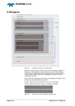
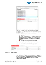
Страница 91: ...ed BITE Built In Test Environment information it is easy to check if each part of the system is working fine It is quickly apparent for instance if a component wire or pin is the cause of an error or warning A BITE snapshot can be saved in HTML format The Service mode is selected in the Sonar UI Toolbar see Service Mode on page 16 This chapter will explain how the user can go through the different...

Страница 92: ... system is working fine All components wires and pins should be in blue or green BITE information is available for the green and red components and pins Click on the item in the diagram to display the available information on the right side on the Details tab see page 81 A green component or pin will turn red if an error is detected A green component will turn orange if a warning is detected Figur...

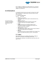
Страница 93: ... Config page Details see page 81 On the Details page the BITE information of the selected component wire or pin in the diagram is displayed Config On the Config page the preconfigured settings and the serial version numbers for the software and firmware of the installed sonar system is displayed IO Module QC see page 83 In the IO Module QC page the different devices that are interfaced through the...

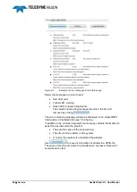
Страница 94: ...ng message will also be displayed in the related BITE information on the Details tab see 5 3 2 below In addition to the error warning itself the message contains information to assist the operator solve the problem The possible cause of the error warning The effect of the problem on the system A hint for the operator to understand the problem Use to save all information of all tabs to a HTML file ...

Страница 95: ...or pin in the diagram will be displayed Press Ctrl B on the keyboard to access more information for some items in the diagram At the top the name and unique ID of the selected component wire or pin is given Below this the available BITE information is displayed with the actual value or status for each item The accepted range for each item is displayed between brackets ...

Страница 96: ...r status which is incremented when there is an error and decreased if not When there are many errors close to each other in time the error status will increment above 1 and the status goes to Error After a while with few or no errors the error status will crawl down and come below 1 the status goes back to Ok The tolerance to the errors and the time errors are remembered are controlled by the min ...

Страница 97: ...is made for the Virtex6 hardware Therefore the Virtex6 items in the Details page will all be zero when Virtex2 hardware is used The operator should ignore the Virtex6 information when Virtex2 hardware is used 5 3 3 IO Module QC In the IO Module QC tab the data from the different devices interfaced and set up in the IO Module are displayed For each device the data string is unpacked and the data is...

Страница 98: ...ule QC page with good heading data When the message is received correctly this is indicated by a green colored ok status box See Figure 5 8 If data from one of the devices is not received properly it is indicated by a red colored time out box See Figure 5 9 ...

Страница 99: ...the required data field is available Invalid data one or more items failed to unpack The status indication is with respect to the last received data block This means the field can still marked as ok while the status box indicates time out As it was received previously correct See Figure 5 10 Figure 5 10 Status indication The raw data as received from the IO Module is displayed These are the data s...

Страница 100: ...86 Service SeaBat Sonar UI User Manual ...

Страница 101: ...Head mode FRDH Sonars ping in a maximum possible rate The full rate mode is an option For a Full Rate Dual Head configuration FRDH the processors must be triggered For this purpose a cable must be connected from the Master processor trigger out socket to the trigger input socket of the Slave processor For a Full Rate Dual Head configuration the transmit pulse type must set in FM for both the Maste...

Страница 102: ... the Dual head mode Tick the checkbox for full rate mode untick the check box for normal ping pong mode In the normal mode the ping delay could be set This delay is inserted before the other head pings to avoid interference with the slave head b Click the arrow key for a drop down list and select the slave processor s IP address A proper network connection between the two processors is required be...

Страница 103: ...el s Centre Reference Point CRP The offsets are from the sonars acoustic center to the CRP of the vessel On the moment of writing it is only for proper indication of the wedge and therefore doesn t need to be set very accurate Enter when applicable the correct head tilt Two wedges appear at the master SUI One for the Master and one for the Slave sonar Hover with the cursor over the head for a Mast...

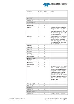
Страница 104: ... Select from the Sonar address in the SUI toolbar the slave IP address It is indicated in the top bar of the display which sonar is displayed at the screen 5 Repeat Step 4 and select the Master IP address This is the major display as the Master controls the Slave 6 3 Control As the Master dictates when the slave sonar will cycle most functions in the Slave Sonar are mirrored from the master and th...

Страница 105: ...ue is changed this will set the slave steering value with the master setting Max Rate X Frequency X X Pulse type X X Absorption X Spreading X Sound velocity X Detection Pane Depth gate X Range gate X Adaptive gate X Tracker X The Tracker mode is enabled from the Master The master will control the Slave settings except the power and gain these are controlled by the slave It is however not possible ...

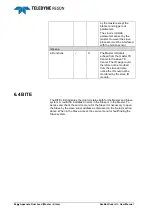
Страница 106: ...r to the slave 7K Center The IO page could therefore not be modified from the slave and also notice the IO could not be monitored by the slave IO module 6 4 BITE The BITE LED indicates the Alarm status both for the Master and Slave system A red BITE indicates an error in the Slave or in the Master To access and check the service menu for the Slave it is necessary to open the Slave by the slave son...

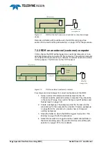
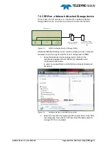
Страница 107: ...file sharing creating a workgroup etc For this document the necessary Windows 7 operating system settings are described This document discusses the setup for RDR but is also applicable for AVI recording 7 2 Scenarios For this document we define five scenarios For a common 7K Gx where x is a generation number processor RDR on a Gx processor RDR on an external customer computer RDR on a Network Atta...

Страница 108: ...n of the RDR 1 Setup a correct IP address and Subnet mask for the 7K Processor and the external customer computer They should be in the same IP range See section Setup correct IP address and Subnet mask on page 100 2 Create a workgroup The workgroup must be the same for the processor as for the computer See section Create a workgroup on page 98 for the procedure to create a new or change an existi...

Страница 109: ...to be performed for correct configuration of RDR 1 Setup the Network access storage device Refer to the manufacture supplied documentation for installation and configuration instructions In common created folders on the NAS are already shared and accessible Figure 7 4 Windows Explorer with NAS drive listed 2 Select the records to be logged and the shared folder in the SUI s recording pane See sect...

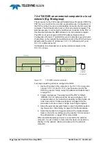
Страница 110: ...rnal computer Four steps needs to perform to configure the RDR 1 Set the IP number of the computer in the 10 11 10 x range Do not use 10 11 10 1 and 10 11 10 2 as these are used by the PSP See section Setup correct IP address and Subnet mask on page 100 2 Create a workgroup The workgroup of the PSP is default RESON It is not really needed to set up a workgroup but computer names in the network are...

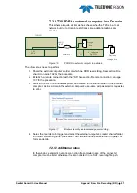
Страница 111: ... the procedure 3 Start on the PSP the Windows Explorer and browse to the shared folder on the external computer As it is a domain the external computer s username and password is requested to enter Figure 7 7 Windows Security username and password dialog 4 Select the records to be logged and select the external computer s created shared folder in the SUI s recording pane See section SUI record and...

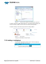
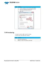
Страница 112: ...ring settings See section file sharing on page 102 how to access the advanced sharing settings It could be necessary to have Home group network file sharing selected Figure 7 9 Home network Contact your administrator in case of issues 7 3 Creating a workgroup The connected computers processors must be in the same workgroup The table below summarizes the procedure Step Action 1 Open the windows sta...

Страница 113: ...ppendix Raw Data Recording RDR 99 Step Action 2 Open the windows Control panel 3 Open System 4 a A overview is listed with the computer name and current Workgroup name b Click Change settings to modify 5 Followed by clicking Change ...

Страница 114: ...the other connected computers processors 7 Click OK when finished 7 4 Setup correct IP address and Subnet mask The table below summarizes the procedure to setup an IP address and a subnet mask Computers processors connected to each other must be in the same range with a unique last digit E g Processor 10 4 0 1 and PC1 10 4 0 2 Step Action 1 Open the windows start menu 2 Open the windows Control pa...

Страница 115: ...e listed with available ports A Local Area connection should be listed with status Connected Check the network connection cable between the processor computer when status is disconnected Right click at this local area connections icon 6 Open the Properties from the context menu 7 Double click Internet Protocol Version 4 TCP Ipv4 ...

Страница 116: ... the following IP address b Enter the IP address In this example 10 4 0 1 c Enter subnet mask 255 255 255 0 d Click OK 7 5 File sharing The folder to store the RDR needs to be shared The table below summarizes the procedure Step Action 1 Open Windows Explorer 2 Make or create a new folder to be shared ...

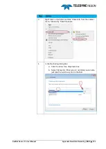
Страница 117: ...tion 3 Right click on this folder and click Share with from the context menu followed by Specific people 4 In the file sharing dialog box a Click the arrow for a drop down box b Select Everyone If Everyone is not listed you can also just type the word everyone in the field ...

Страница 118: ...4 Appendix Raw Data Recording RDR SeaBat Sonar UI User Manual Step Action 5 Click Add 6 Click the arrow to change the Permission Level from Read into Read Write Click the Share button to share the folder ...

Страница 119: ...xplorer it is indicated if a folder is shared with its properties 7 5 1 1 Additional settings In order to share folders it could be necessary to setup additional settings These settings could be done in the Control panel Network and Sharing Center The following table summarizes the procedure Step Action 1 Open the windows start menu ...

Страница 120: ... Open the Network and Sharing Center 4 Click Change advanced sharing settings 5 Click the chevron to see the network settings Be aware to select the correct profile 6 All kind of advanced settings are listed A setting which could cause problems is the password protected sharing Turn this password protection off ...

Страница 121: ... es 3 Double click the file storage path field 4 Browse to the folder When the folder is on an external computer browse to Network and the computer name of this external computer followed by the associated shared folder 7 7 Remote connection The T20 Portable sonar Processor is accessible by a remote desktop connection from an external computer The table below summarizes the procedure to setup a re...

Страница 122: ...te connection is used for advanced trouble shooting or setup Note when logged in a domain it is necessary to enter for the username the PSP s IP address followed by RESON E g 10 4 1 1 RESON 7 8 Start RDR Click in the SUI s toolbar at RDR to start the logging Figure 7 10 Click RDR to start the logging When the logging runs this is indicated by green LED Figure 7 11 green LED See Figure 7 12 a The f...

Страница 123: ...SeaBat Sonar UI User Manual Appendix Raw Data Recording RDR 109 Figure 7 12 File storage data Click in the SUI s toolbar RDR again to stop the logging ...

Страница 124: ......

Страница 125: ...n and or other materials provided with the distribution The name of the author may be used to endorse or promote products derived from this software without specific prior written permission THIS SOFTWARE IS PROVIDED BY THE COPYRIGHT HOLDERS AND CONTRIBUTORS AS IS AND ANY EXPRESS OR IMPLIED WARRANTIES INCLUDING BUT NOT LIMITED TO THE IMPLIED WARRANTIES OF MERCHANTABILITY AND FITNESS FOR A PARTICUL...

Страница 126: ... AN ACTION OF CONTRACT TORT OR OTHERWISE ARISING FROM OUT OF OR IN CONNECTION WITH THE SOFTWARE OR THE USE OR OTHER DEALINGS IN THE SOFTWARE Copyright c 2007 The Khronos Group Inc Permission is hereby granted free of charge to any person obtaining a copy of this software and or associated documentation files the Materials to deal in the Materials without restriction including without limitation th...

Страница 127: ...Depth Gate Tilt 40 Detect 45 72 Detection 38 Diagram 16 78 Display 22 44 Docking 6 E Equi Angle 27 Equiangular 27 Equidistant 28 Equi distant 28 External Clock 35 F Flex Steering 62 63 Flexmode 28 Floating 7 FM 32 54 Frequency 4 31 32 G Gain 4 24 Guide Diamonds 7 H Hardware 50 Heading 35 48 helmsman 74 Help 16 Helsman 26 Horizontal Steering 30 62 63 HTML File 80 I Input distribution RRIO 36 Interm...

Страница 128: ...4 32 R Range 4 23 Range Gate 40 Rate 25 Recording 23 47 Remote desktop 14 Reset 12 Restore factory settings 13 Roll Stabilization 4 18 51 S S7K File 17 35 47 Salinity 32 Service 16 Side lobes 57 Sidescan 26 72 Snapshot 16 Snippets 26 48 73 Sonar Address 16 Sonar network connections 14 Sound Velocity 30 33 35 48 Spreading 32 33 SVP Filter 33 T Toolbar 12 Tracker 17 55 Trigger Configuration 53 TVG 2...

Отзывы:

Похожие инструкции для UI