
Telecast Fiber Systems
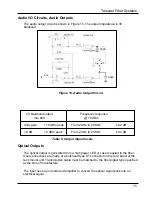
Audio I/O Circuits, Audio Outputs
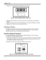
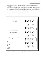
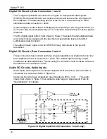
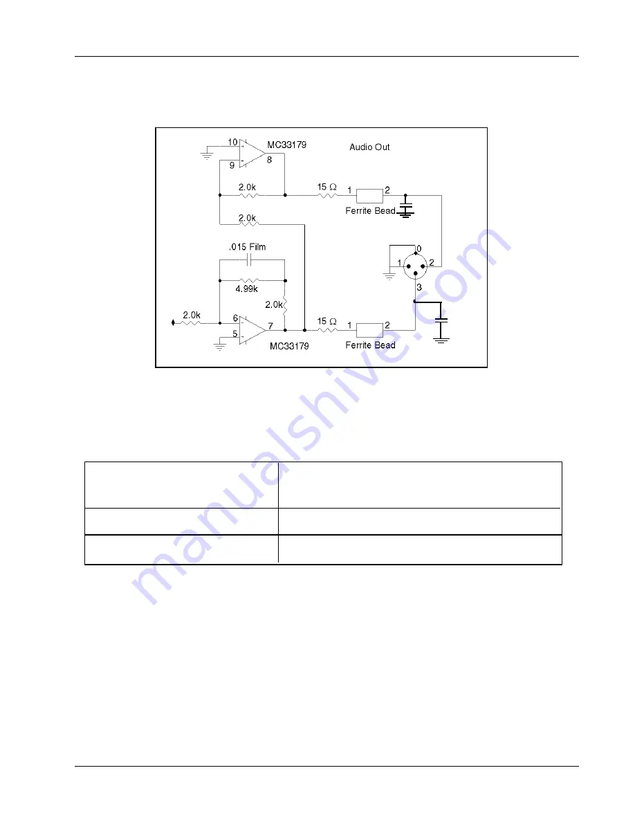
The audio output circuit is shown in Figure 15. The output impedance is 30 ,
balanced.
100pF
100pF
Figure 15. Audio Output Circuit
30 Balanced output
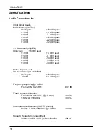
Frequency response
into 600
@ +8 dBm
Unity gain
+18 dBm peak
From 20 Hz to 25 KHz
±0.2 dB
-10 dB
+8 dBm peak
From 20 Hz to 25 KHz
±0.2 dB
Table 6. Output Signal levels
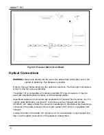
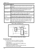
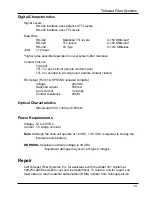
Optical Outputs
The optical output is generated from a high power LED or Laser coupled to the fiber.
User connections are made at a bulkhead type ST connector on the rear panel of the
rack mount unit. Transmission cable must be matched to the fiber pigtail type specified
at the time of manufacture.
The input uses a pin diode and amplifier to convert the optical signal back into an
electrical signal.
15
Содержание Adder 161
Страница 2: ...Adder 161 ii...
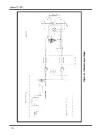
Страница 18: ...Adder 161 Figure 14 TX Audio Input Stage 14...
Страница 25: ...Telecast Fiber Systems 21...


