background image

Adder™ 161

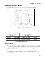
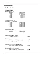
Audio I/O Circuits, Audio Inputs

Audio inputs and outputs are on sixteen separate XLR connectors, each of which is

       connected to a circuit as shown in Figure 14.

Inputs can be set to have a balanced input impedance 600 or 10 K. 

The audio

       input circuit shown in Figure 14 can accept a wide range of signal levels. Refer to
       “Specifications”  for details.

+5

5 9 4 8 3 7 2 6 1

Data I/O

IN

OUT

-

-

+

+

10k

100k

.1

74HC14A

Data to
Multiplexer

+5

39k

10k

10k

39k

22pf

22pf

10k

10k

MAX909

+

-

Data to
Multiplexer

+5

-5

BAT54S

1

2

3

4 5

6

7

8

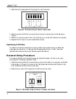
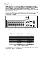
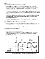
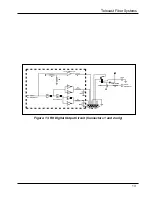
Figure 12. Digital Input Circuit (Connectors 1 and 2 only)

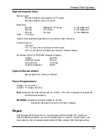
Digital I/O Circuits, Data Connectors 1 and 2

Digital I/O Circuits, Data Connectors 3 and 4

These connectors have contact and relay closure capability only. Digital data can only

       be accepted and sent on connectors 1 and 2. The contact input and relay output

circuits are as described above. The pin wiring for connector 3 and 4 closure circuits is

       the same as on connectors 1 and 2.

The TX digital input buffer circuit shown in Figure 12 accepts both data signals
(RS-232, RS-422 and RS-423) and contact closures and delivers this information to

       the multiplexer. The data handling portion of the circuit is connected only to DB-9
       subminiature data connectors 1 and 2.

It also accepts a contact closure indicated by the switching of pin 8 to ground level, pin

       3. This can also be accomplished by a TTL connection closure with pin 3 as the ground
       reference.

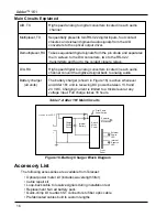
The RX digital output buffer circuit shown in Figure 13 accepts the demultiplexed data

       and contact closure signals and provides them at appropriate levels to the DB-9

subminiature data connector.

The output closure output is via an SPST-NO relay; this closure is not ground
referenced.

12

Содержание Adder 161

Страница 1: ...Telecast Fiber Systems Inc 102 Grove Street Worcester MA 01605 Tel 508 754 4858 Fax 508 752 1520 www telecast fiber com Adder 161 Audio Multiplexer Instruction Manual...

Страница 2: ...Adder 161 ii...

Страница 3: ...Electrical Connections 7 Audio Connections 7 Digital Connections 8 48 VDC Phantom Power 9 Line Power Connection 9 Input Power Fuse 9 Battery Charging 10 Panel Indicators 10 Powering Up 11 Theory of Op...

Страница 4: ...se Locations 9 Figure 10 TX and RX Front Panel 10 Figure 11 Electronic Block Diagram 11 Figure 12 TX Digital Input Circuit Connectors 1 2 only 12 Figure 13 RX Digital Output Circuit Connectors 1 2 onl...

Страница 5: ...manual Within an Adder 161 TX transmitter unit the audio signals are first digitized and then multiplexed with the digital control signals The combined electrical signal is converted to an optical sig...

Страница 6: ...wer supplies require 120 VAC Be sure that AC outlets are within reach of their 6 foot power cords Fiber and Coaxial Cable Runs The installer is responsible for providing the fiber optic cable runs whi...

Страница 7: ...k 40 dB 22 dBm peak 40 dB 24 dBV peak 50 dB 32 dBm peak 50 dB 34 dBV peak Audio Signal Setup Note Setting up the internal switches on the rack mount unit requires removal of its top cover The DIP swit...

Страница 8: ...dBm the input gain can be set to 10 dB and the RX attenuation set to 10 dB Thus the signal levels remain at the same reference level throughout Receiver Setup Procedure The setup switches for the outp...

Страница 9: ...the Fine Level trim pot in each output circuit of the Adder 161 RX The range of adjustment is 2 dB 5 If the system is to be used with coaxial cable rather than fiber move the small switch near the al...

Страница 10: ...are available from Telecast Fiber Systems Inc For custom cable fabrication use type ST connectors such as Telecast part number CONN ST QC Always follow the connector manufacturer s directions when fa...

Страница 11: ...locations See Table 3 and Figure 7 Pin Signal 1 Ground 2 Balanced I O 3 Balanced I O Table 3 XLR Audio I O Cable Connections The XLR connectors are on the rear panel as shown in Figure 7 Transmitter...

Страница 12: ...ia the DB 9 connectors as shown in Figure 8 The connection specifications are listed in Table 4 A 110 terminating resistor placed across the balanced inputs may be needed if cable lengths are in exces...

Страница 13: ...ly into a 120 VAC line See Figure 9 for locations followed by Table 5 for connections AUDIO DA TA 1 CLOCK COAX DAT A I O SLO DC INPUT 12 24 VDC 2 3 4 OPTICAL 1 3 5 7 9 11 13 15 2 4 6 8 10 12 14 16 1 4...

Страница 14: ...fter one half hour of charging There may be a few minutes of reserve power after the indicators turn off Rx Status This red LED on the receiver is on when the fiber optic link is not properly attached...

Страница 15: ...digital inputs and time division multiplexes them onto a single optical fiber or coaxial cable The system has two basic functions multiplexing signals onto an optical fiber or coaxial cable and demul...

Страница 16: ...e accepted and sent on connectors 1 and 2 The contact input and relay output circuits are as described above The pin wiring for connector 3 and 4 closure circuits is the same as on connectors 1 and 2...

Страница 17: ...Multiplexer A B C D E F 51 51 51 10k 10k 1 of 4 MC33179 6 of 74HC14 180pf 180pf 5 9 4 8 3 7 2 6 1 Data I O Data from De Multiplexer FMMT2222A FMMD6100 1k 10 16 5v 5 IN OUT Figure 13 RX Digital Output...

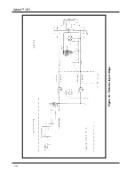
Страница 18: ...Adder 161 Figure 14 TX Audio Input Stage 14...

Страница 19: ...2 dB 10 dB 8 dBm peak From 20 Hz to 25 KHz 0 2 dB Table 6 Output Signal levels Optical Outputs The optical output is generated from a high power LED or Laser coupled to the fiber User connections are...

Страница 20: ...wn in Figure 16 is active whenever all units an Adder 161 unit is receiving DC power between 13 8 and 24 VDC Charging current is limited to a trickle level at any voltage input Full charge takes 16 ho...

Страница 21: ...power depleted adapter If the light does not turn green replace the battery No operation Fiber or coax Check for broken or disconnected rx status LED on communications fibers and faulty wires or that...

Страница 22: ...6 dBV peak 20 dB 4 dBV peak 30 dB 14 dBV peak 40 dB 24 dBV peak 50 dB 34 dBV peak Output Signal Levels 30 balanced output into 600 W Unity gain 18 dBm peak 10 dB 8 dBm peak Frequency response 8 dBm Fr...

Страница 23: ...p 0 19 2 KBits sec Jitter 1 12 msec higher rates possible dependent on user system jitter tolerance Contact Closure TX Input TTL 1 or open circuit remote contact open TTL 0 or shorted to circuit groun...

Страница 24: ...ate maintenance and care Nor shall this warranty apply to any damage caused in whole or in part by attempts by personnel other than Telecast s personnel as approved in advance in accordance with the f...

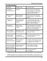
Страница 25: ...Telecast Fiber Systems 21...

Отзывы: