background image

29

Installing the Equipment

2.5.6.2

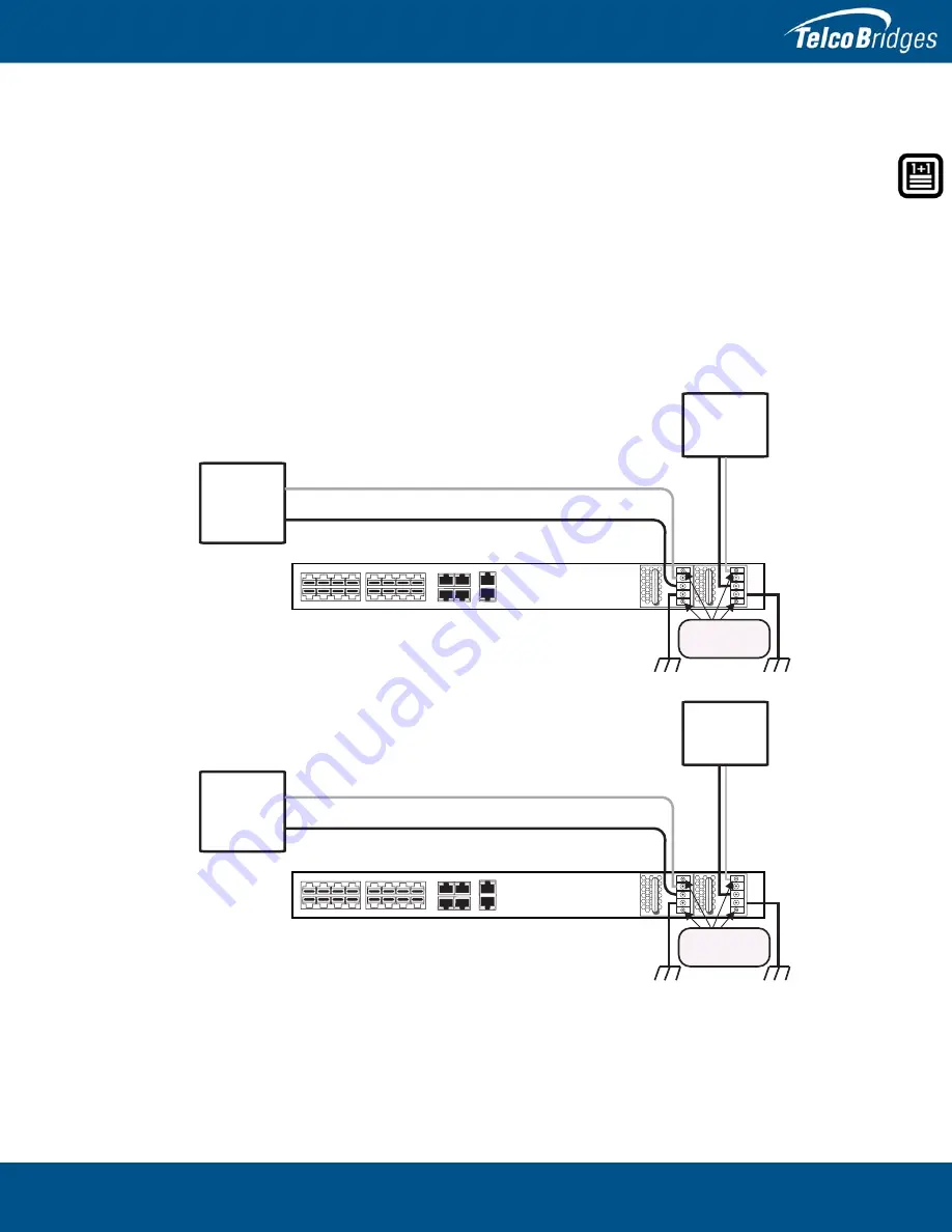
Connecting to DC Power

The 800 series gateway, DC model, is furnished with two DC power supplies. 

To connect an 800 Series and 800 1 Unit to DC Power

1.

Connect one wire from the positive terminal of the 800 series gateway to the return side of DC 
power source one, as shown in 

figure


2.7 on page

 19.

2.

Connect another wire from the negative terminal of the 800 series gateway to the -48V side of DC 
power source one.

3.

Connect a ground wire from the ground terminal of the 800 series gateway to earth ground.

4.

Repeat steps 1-3 for the second power DC power source.

Figure


2.14

800 Series Gateway Redundant DC Supply Wiring Diagram

DC

Power

Source 1

DC

Power

Source 2

+ (positive)

- (ne

g

ative)

Earth Ground

Power Supply
Mountin

g

 Screws

Do not unscrew

+ (positive)

- (ne

g

ative)

15

14

13

12

10 11

8

9

3

2

0

7

6

5

4

1

MGMT0

MGMT1

ETH0

ETH1

VOIP0

VOIP1

DC

Power

Source 1

DC

Power

Source 2

+ (positive)

- (ne

g

ative)

Earth Ground

Power Supply
Mountin

g

 Screws

Do not unscrew

+ (positive)

- (ne

g

ative)

15

14

13

12

10 11

8

9

3

2

0

7

6

5

4

1

MGMT0

MGMT1

ETH0

ETH1

VOIP0

VOIP1

Содержание 800 1+1 series

Страница 1: ...Installation Guide 800 Series Gateway Standalone 800 Series Gateway 1 1 October 26 2015...

Страница 2: ...ommitted to continually improving product designs as a result product specifications may be subject to change without notification 2003 2015 TelcoBridges All rights reserved TelcoBridges Tmedia TMG800...

Страница 3: ...s to all variations of the 800 series 1 units such as TMG800 1 TSG800 1 or TMGIP800 1 1 1 Patch Panel This term is used as a generic reference to a 1 1 patch panel which enables an 800 series unit to...

Страница 4: ...Standalone and 800 Series 1 1 System Installation Guide iv Contact Us If you have comments about this guide or any other TelcoBridges technical documentation please send an email to marketing telcobr...

Страница 5: ...cting to the PSTN 16 2 4 4 Grounding the Equipment Chassis 17 2 4 5 Powering Up 18 2 4 5 1 Connecting to AC Power 18 2 4 5 2 Connecting to DC Power 19 2 4 6 Start Up 20 2 4 6 1 Configuring the Role 20...

Страница 6: ...uring the Terminal Emulator Application 44 3 4 Connecting to the 800 Series Gateway 44 3 5 Retrieving 800 Series Gateway Information 45 3 6 Changing the 800 Series Gateway Management Port IP Address 4...

Страница 7: ...erating in standalone mode 800 series 1 1 system 800 series unit operating in conjunction with an 800 series 1 unit and 1 1 patch panel s The following topics are covered Section 1 1 Recognizing an 80...

Страница 8: ...2 1 1 2 800 Series 1 1 System The 800 series 1 1 system see figure 1 1 on page 2 consists of One telecom unit One 1 telecom unit One or two 1 1 patch panels Figure 1 1 Equipment Front and Rear Views 1...

Страница 9: ...ectricity each power connection must be fed by a dedicated power source IP addresses for the management ports To avoid delays you should have the IP address netmask and gateway addresses on hand Take...

Страница 10: ...the wrist strap and cord must be in proper working condition If no wrist strap is available and you must work with the equipment ground yourself by touching a metal part of the chassis 1 4 Recommende...

Страница 11: ...unting the 800 Series Standalone or the 800 Series 1 1 System Section 2 3 Choosing your Connection Procedures Section 2 4 800 Series Standalone Section 2 5 800 Series 1 1 System Section 2 6 Adding an...

Страница 12: ...ems One 800 series unit TMG800 TSG800 or TMGIP800 See figure 1 1 on page 2 One set of mounting brackets and screws used to mount the 800 series unit to a 19 rack One Tmedia serial adapter to interface...

Страница 13: ...s One or two DC power cables Not included A 19 equipment rack The 800 series unit must be installed in a standard 19 wide equipment rack TMG800 1 TSG800 1 TMGIP800 1 One 800 1 series unit See figure 1...

Страница 14: ...the 800 series 1 1 system Cables provided You are provided with 16 RJ48C cables yellow two meters in length with your 1 1 Patch Panel 8 T1 E1 Table 2 1 1 1 Patch Panels for TMG800 1 and TSG800 1 1 1...

Страница 15: ...standalone 800 series 1 and 1 1 Patch Panel are each housed in a 1U chassis as tabulated in table 2 2 on page 9 It is important that you provide for enough room on the equipment rack to allow for the...

Страница 16: ...t as shown in figure 2 1 on page 11 Do the same for the angle bracket on the right hand side 2 Start mounting equipment at the top most position of the rack keeping in mind the space required on the e...

Страница 17: ...Mounting the Equipment 800 Series Unit 800 Series 1 Unit 1 1 Patch Panel 800 Series Unit 800 Series Standalone 800 Series 1 1 System Network Gateway Gateway 1 1 Patch Panel 8 T1 E1 1 1 Patch Panel Net...

Страница 18: ...ur Setup 800 Series Standalone I am setting up an 800 series as a standalone unit I am setting up an 800 series 1 1 system including an 800 series unit 800 series 1 and 1 1patch panel s creating a red...

Страница 19: ...p as a standalone system This section covers the following procedures Section 2 4 1 Connecting to the 800 Series Gateway Management Interface Section 2 4 2 Connecting to a VoIP Network Section 2 4 3 C...

Страница 20: ...e port labeled MGMT0 at the rear of the 800 series gateway Connect the other end of the same CAT5 cable to the first gigabit Ethernet switch 2 If your system employs a second gigabit Ethernet switch f...

Страница 21: ...undancy of the VoIP interface One or two CAT5 Ethernet cables with RJ45 male male terminations Connections The 800 series gateway is connected to the VoIP network by one or optionally two Ethernet Gig...

Страница 22: ...aking your own cables refer to Section A 1 RJ48C Wiring Diagram Crossover and Straight Cables on page 51 for crossover or straight cable wiring connections Note All of the ports may not be active T1 E...

Страница 23: ...s short as possible Do NOT daisy chain the ground between equipment Use a ground bus bar as show in figure 2 5 on page 17 Do not over tighten ground lug connections To connect the 800 series gateway t...

Страница 24: ...requisites To power the 800 series gateway you will need Two power sources Two power cables for the 800 series gateway To connect to AC Power 1 Connect an AC power cable to each AC connector of the 80...

Страница 25: ...ire from the negative terminal of the 800 series gateway to the 48V side of DC power source one 3 Connect a ground wire from the ground terminal of the 800 series gateway to earth ground 4 Repeat step...

Страница 26: ...your 800 series gateway starts up and displays the web portal configuration management tool Note To learn about the IP address for your system or how to change it refer to Section 3 6 Changing the 800...

Страница 27: ...2 5 1 Connecting to the 800 Series 1 1 System Management Interfaces Section 2 5 2 Connecting to the 800 Series 1 1 System Control Network Section 2 5 3 Connecting to the 800 Series 1 1 System VoIP Net...

Страница 28: ...the first gigabit Ethernet switch 2 If your system employs a second Gigabit Ethernet switch for redundancy connect a second CAT5 Ethernet cable to MGMT1 at the rear of the 800 series gateway Connect...

Страница 29: ...Ethernet cables with RJ45 male male terminations To connect to the VoIP network 1 Connect one CAT5 Ethernet cable between ports ETH0 of both the 800 series and 800 series 1 units 2 Connect a second C...

Страница 30: ...ches A second one is required to support redundancy of the VoIP interface Four CAT5 Ethernet cables with RJ45 male male terminations Connections The 800 series unit and 800 series 1 VoIP ports must to...

Страница 31: ...ber of active ports depends on the licenses purchased Patch panels use straight connections In other words they do not cross the RX and TX signals Connections between the patch panels and an 800 serie...

Страница 32: ...twork Gateway Gateway 1 1 Patch Panel 8 T1 E1 TMG800 TSG800 TMG800 1 TSG800 1 800 Series Unit 800 Series 1 Unit From Network 15 14 13 12 10 11 8 9 3 2 0 7 6 5 4 1 MGMT0 MGMT1 ETH0 ETH1 VOIP0 VOIP1 15...

Страница 33: ...h a 10 ring terminal Keep the length of the ground wire as short as possible Do NOT daisy chain the ground between equipment Use a ground bus bar as show in figure 2 12 on page 27 Do not over tighten...

Страница 34: ...er cables for every 800 series and 800 series 1 unit 2 5 6 1 Connecting to AC Power To connect to AC Power 1 Connect the first power connector of each unit to the first power source See Figure 2 13 2...

Страница 35: ...C power source one 3 Connect a ground wire from the ground terminal of the 800 series gateway to earth ground 4 Repeat steps 1 3 for the second power DC power source Figure 2 14 800 Series Gateway Red...

Страница 36: ...play the web portal configuration management tool Note To learn about the IP address for your system or how to change it refer to Section 3 6 Changing the 800 Series Gateway Management Port IP Address...

Страница 37: ...31 Installing the Equipment 3 Once you confirm the changes a progress page is displayed...

Страница 38: ...Series 1 1 System Section 2 6 2 Install the 800 Series 1 unit on the Equipment Rack Section 2 6 3 Install the 1 1 Patch Panel Section 2 6 4 Connect to the 800 Series 1 1 Management Interface Section 2...

Страница 39: ...33 Installing the Equipment 3 Select a host from the Host Configuration List 4 Select the Status tab...

Страница 40: ...eries Standalone and 800 Series 1 1 System Installation Guide 34 5 Select Reset Host Role 6 Follow the instructions of the web portal to configure your unit as a primary unit in a new 800 series 1 1 s...

Страница 41: ...connect to the 800 series control network which allows both units to communicate with each another If you are installing an 800 series 1 unit the associated one or two 1 1 patch panels will look like...

Страница 42: ...E1 interfaces for connection to the PSTN network 2 6 8 Power Up the Equipment The 800 series and 800 series 1 units are furnished with one 1 or two 2 AC or DC power connections Only once all other equ...

Страница 43: ...for your system or how to change it refer to Section 3 6 Changing the 800 Series Gateway Management Port IP Address on page 45 1 Connect to the web portal of the 800 series 1 1 system The Welcome pag...

Страница 44: ...cation is normal See Table 2 3 on page 38 Table 2 3 800 Series Unit Displays Note An alarm will sound if one of the power supplies is faulty There is no alarm button to disable the alarm To stop the a...

Страница 45: ...DO NOT TURN OFF the power to the 800 series gateway unless you have already performed the previously mentioned shut down procedure Allow enough time for the VoIP gateway to shut down before turning th...

Страница 46: ...800 Series Standalone and 800 Series 1 1 System Installation Guide 40...

Страница 47: ...on 3 3 Configuring the Terminal Emulator Application Section 3 4 Connecting to the 800 Series Gateway Section 3 5 Retrieving 800 Series Gateway Information Section 3 6 Changing the 800 Series Gateway...

Страница 48: ...nterface enables administrators to perform management tasks on the 800 series gateway To connect to the Type B USB serial port of an 800 series gateway 1 Connect the Type A USB connector of the USB ca...

Страница 49: ...d with unit Connect the DB9 to RJ 45 to the serial port of the computer and the other end of the CAT5 RJ 45 male male cable to the serial port labeled 10101 of the 800 series gateway as shown in figur...

Страница 50: ...3 Set the parity to None 4 Set the stop bits to 1 5 Set the flow control to None Note See Section 3 6 on page 45 to learn how to change the IP address of the MGMT0 port 3 4 Connecting to the 800 Seri...

Страница 51: ...series 1 1 system Each 800 series gateway has two management ports mgmt0 and mgmt1 They are configured in bonding by default and the values are located on the Important Notice sheet It can be modified...

Страница 52: ...llation Guide 46 3 8 Setting the Time Zone Note The following procedure must be performed on the 800 series standalone unit and the 800 series 1 1 system You can change the time zone of the 800 series...

Страница 53: ...the Web Portal System Configuration Tutorial Guide found on the TBWiki http docs telcobridges com The Web Portal can be accessed with a Web browser The default url is http Tmedia MGMT0 IP address 123...

Страница 54: ...800 Series Standalone and 800 Series 1 1 System Installation Guide 48...

Страница 55: ...ps This section provides information about the following topics Section 4 1 Creating a Database Backup Section 4 2 Downloading a Database Backup Section 4 3 Uploading a Database Backup Section 4 4 Res...

Страница 56: ...made once the system has been configured Backups are performed using the web portal 4 2 Downloading a Database Backup A backup of system data is stored on the hard drive of the 800 series gateway It...

Страница 57: ...T1 E1 Wiring Schematic Crossover Cable 1 8 RX Ring 1 RX Tip 2 Not Connected 3 TX Ring 4 TX Tip 5 Not Connected 6 Not Connected 7 Not Connected 8 1 RX Ring 2 RX Tip 3 Not Connected 4 TX Ring 5 TX Tip 6...

Страница 58: ...dalone and 800 Series 1 1 System Installation Guide 52 A 2 Tmedia Serial Adapter Wiring Diagram 1 N C 2 Rx 3 Tx 4 N C 5 GND 6 N C 7 N C 8 N C 9 N C 1 N C 2 N C 3 N C 4 GND 5 Tx 6 Rx 7 N C 8 N C DB 9 R...

Отзывы: