P6021
SECTION
2
OPERATING INSTRUCTIONS
General
The P602 1 Current Probe, when used wtih a P602 1 Termi
nation and an oscilloscope, provides a means of measuring
alternating current waveforms. To effectively use the P602 1,
the operation and capabilities of the probe should be
known. This section gives first-time and general operating
information and some basic applications for the probe.
Installation
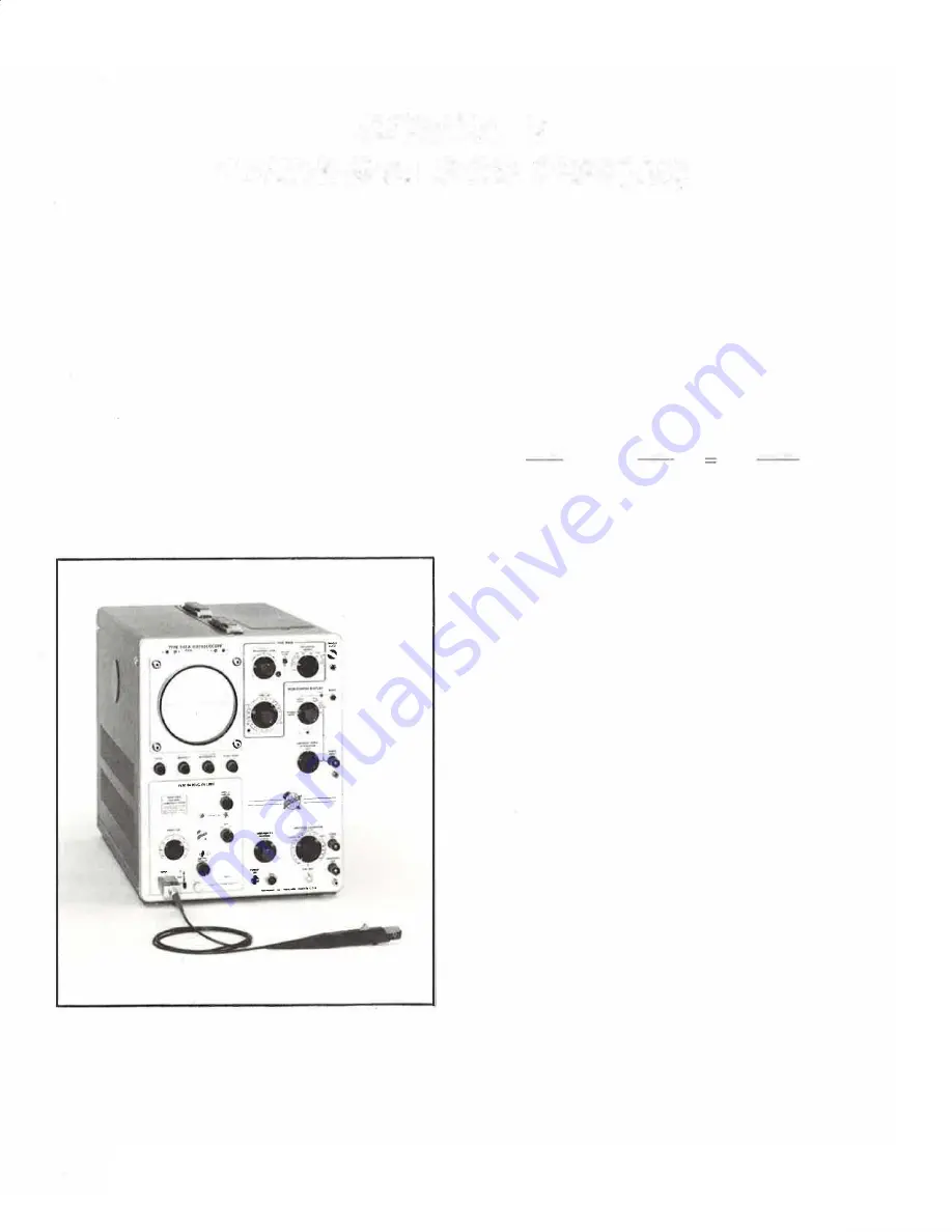
When the P602 1 Current Probe is used with the Termi
nation, an oscilloscope having a vertical amplifier in
put impedance of one megohm is required. The probe
and termination contain adjustments to optimize perform
ance, matching the input characteristics of the vertical am
plifier. To use the probe, first connect the P6021 Termination
to the vertical input of the oscilloscope. Then connect the
P602 1 Current Probe to the termination (see Fig. 2-1).
Fig. 2-1. The P602 1 Current Probe and Termination connected to
a test oscilloscope.
Sensitivity Control
The P602 1 Termination has a slide switch which changes
the sensitivity of the probe and termination by a factor of
2-1
five. With the switch in the 2 mA/mV position, a current
change of two milliamperes in the conductor under test is
seen as a change of one millivolt at the vertical input. In
the 10 mA/mV position, a change of ten milliampere pro
duces one millivolt at the vertical input. The oscilloscope
deflection factor may be set to any position, depending
upon the amplitude of the signal. The overall deflection
factor including the probe and termination may be found
quickly by multiplying the slide switch position by the oscil
loscope deflection factor. The following is an example:
Termination switch setting
1 0 mA/mV
Volts/div switch setting
20 mV/div
1 0 mA
20 mV
200 mA
mV
X
div
div
Probe Slider
The thumb-controlled probe slider opens the transformer
core located in the end of the probe and closes it around
the conductor under test. The conductor under test becomes
the primary of the transformer when the core is closed.
When measurements are being made, the slider should
always be pushed all the way forward, as this applies pres
sure to the movable portion of the transformer core, assur
ing complete contact to the stationary portion of the trans
former core.
GENERAL OPERATING INFORMATION
Ground Clip Leads
Ground clip leads are furnished with the probe to ground
the shield around the probe transformer at the probe end of
the cable when desired. When observing high frequency
waveforms, use the short ground clip lead to avoid ringing.
Direction of Current Flow
Direction of conventional current flow, as opposed to
electron flow, is plus to minus. Conventional current flowing
in the direction of the arrow on the probe produces a posi
tive deflection of the waveform on the CRT (see Fig. 2-2).
Loading Effect
To minimize loading effect of critical circuits, clamp the
probe at the low or ground end of a component lead when
ever possible. Also, less noise or spurious signal interference
will be seen when the probe is connected near ground.
Содержание P6021
Страница 3: ...Verso Filler Page z z ...
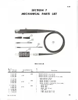
Страница 4: ...Fig 1 1 P6021 Current Probe and Termination ...


