Performance Check! Calibration-P6021
4.
Check Sensitivity
a. Remove the P6021 Probe, Termination, and Calibration
Fixture from the test equipment.
b. Connect two 50-ohm GR
lOX
attenuators and a five
nanosecond length of RG 213/U cable to the output of the
'
pulse generator.
c. Connect the other end of the cable through the 50-ohm
GR to BNC termination to the input of the test oscilloscope.
d. Turn the sweep magnifier off and adjust the amplitude
of the pulse generator output for four centimeters of deflec
tion. See Fig. 5-5A.
e. Remove the attenuators, cable, and termination and
replace with the P6021 Probe, Termination, and Calibration
Fixture. Set the termination slide switch to the 2 mA/mV
position.
f. CHECK-CRT display for four centimeters of deflection,
±3% (not including GR attenuator error). See Fig. 5-5B.
g. Remove the P6021 Probe, Termination, and Calibration
Fixture from the test oscilloscope.
h. Connect two 50-ohm GR
lOX
attenuators, one 50-ohm
GR 5
X
attenuator, and a five-nanosecond length of RG
213/U cable to the output of the pulse generator.
i. Connect the other end of the cable through the 50-ohm
GR to BNC termination to the input of the test oscilloscope.
j. Adjust the amplitude of the pulse generator output for
four centimeters of deflection. See Fig. 5-5A.
k. Remove the attenuators, cable, and termination and
replace with the P6021 Probe, Termination, and Calibration
Fixture. Set the termination slide switch to the 1 0 mA/mV
position.
I. CHECK-CRT display for four centimeters of deflection,
±3% (not including GR attenuator error). See Fig. 5-5B.
5.
Check Low Frequency Response
a. Connect the banana plug to BNC adopter, the BNC
male to GR adapter, and the Calibration Fixture to the out
put of the low-frequency signal generator. Connect the
P6021 Probe to the Calibration Fixture.
b. Set the test oscilloscope Time/Cm switch to 2 ms and
the termination slide switch to the 2 mA/mV position.
c. Set the signal generator frequency to 50 kHz and ad
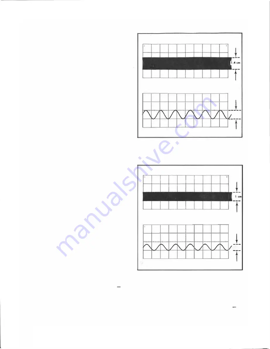
just the output level for 1.4 centimeters of vertical deflec
tion. See Fig. 5-6A.
d. Lower the frequency of the signal generator until the
amplitude of the display reduces to one centimeter. See
Fig. 5-6B.
e. CHECK-Signal generator frequency setting of <450
hertz.
f. Set the test oscilloscope Vo/ts/Cm to .01 V, Time/Cm
to 5 ms, and the termination slide switch to the 1 0 mA/mV
position.
g. Set the signal generator frequency to 50 kHz and ad
just the output level for one centimeter of vertical deflection.
See Fig. 5-7 A.
5-5
(A)
I
•
I
cm
(B)
Fig.
5-6.
Low-frequency response check, 2 mA/mV, showing (AI
1.4-centlmeter,
50 kHz
display, and (Bl ane-centimeter display.
(AI
,
0.7em
(BI
Fig.
5-7.
Low-frequency response check,
10
mA!mV, showing (AI
one-centimeter,
50 kHz
display, and (BI O.T-centimeter display.
h. Lower the frequency of the. signal generator until the
amplitude of the display reduces to 0.7 centimeter. See
Fig. 5-7B.
i. CHECK-Signal generator frequency setting of < 1 20
hertz.
j. Disconnect all test equipment and replace the termi
nation cover.
Содержание P6021
Страница 3: ...Verso Filler Page z z ...
Страница 4: ...Fig 1 1 P6021 Current Probe and Termination ...


