background image

Fig. 

Index 

No. 


10 

1 1  

Tektronix 

Part  No. 

01 1 -01 05-00 

-

-

-

_

 .... 

-

200-0852-08 

1 31 -0602-00 
426-0423-03 

131-0106-02 

670-1052-00 

- ..  ..  - - -

214-1 1 08-00 

388-1212-00 

..  ...  ..  ..  ...  .. 

361-0219-00 

210-1008-00 

21 0-0053-00 

21 1-0001-00 

200-0851-03 

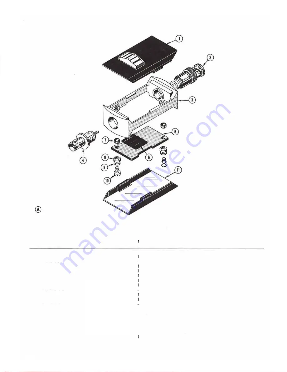
Mechanical  Parts  List-P6021 

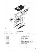
P6021  TERMINATION 

Serial/Model  No. 

Eff 

Disc 

1  2  J  4  5 

TERMINATION,  P6021 

termination  includes: 

Description 

COVER,  termination,  top,  w /knob 
CONNECTOR,  electrical,  BNC,  male 
FRAME,  termination 

CONNECTOR,  BNC,  female 

ASSEMBLY,  circuit  board 

assembly  includes: 
INSULATOR,  plate 

BOARD,  circuit 

mounting  hardware:  (not  included  w/assembly) 

SPACER,  sleeve,  0.087  ID 

0.1 87  inch  OD 

WASHER,  fiat,  0.090  ID 

0.188  inch  OD 

LOCKWASHER,  split,  #2 

SCREW,  2-56 

1/4  inch,  RHS 

COVER,  termination,  bottom 

7-3 

Содержание P6021

Страница 1: ...IMfJuu1iD1t MIJIWlIl P6021 CURRENT PROBE AND TERMINATION Tektronix Inc P O Box 500 Beaverton Oregon 97077 Phone 644 161 Cables Tektronix 070 0947 00 First Printing MAR 1969 Revised MAY 1981 ...

Страница 2: ...ion of Tektronix Inc Products of Tektronix Inc and its subsidiaries are covered by U S and foreign patents and or pending patents TEKTRONIX TEK SCOPE MOBILE and are registered trademarks of Tektronix Inc TELEQUIP MENT is a registered trademark of Tektronix U K Limited Printed in U S A Specification and price change privileges are reserved ...

Страница 3: ...Verso Filler Page z z ...

Страница 4: ...Fig 1 1 P6021 Current Probe and Termination ...

Страница 5: ... Aberrations Probe and Termination only 2 mA mV and 4 4 or less not to exceed 10 mA mV 5 peak to peak within 50 nanoseconds of step 1 1 or less total not to exceed 2 peak to peak thereafter Risetime Probe and Termination only 2 mA mV 4 5 nanoseconds or less 10 mA mV 4 nanoseconds or less Characteristic Risetime with 580 Series test oscillo scope 2 mA mV 10 mA mV Tilt 2 mA mV 10 mA mV Sensitivity A...

Страница 6: ...depending upon the amplitude of the signal The overall deflection factor including the probe and termination may be found quickly by multiplying the slide switch position by the oscil loscope deflection factor The following is an example Termination switch setting 1 0 mA mV Volts div switch setting 20 mV div 1 0 mA 20 mV 200 mA mV X div div Probe Slider The thumb controlled probe slider opens the ...

Страница 7: ...ing Instructions P6021 2 8 pH 1 7 nH 004 n Fig 2 3 Insertion impedance of the P6021 Current Probe the probe is clamped around a conductor When observing fast rise signals this should be taken into consideration Fig 2 3 illustrates the approximate insertion impedance of the P602 1Current Probe Probe Shielding The current probe is shielded to minimize the effect of external magnetic fields However s...

Страница 8: ...fference in level between the pulses induced in the paralled windings of the secondary and matches the balanced probe winding to the cable 3 1 As indicated on the probe body the turns ratio of the P6021 Curent Probe is 125 1 This refers to the number of windings in the secondary of the probe transformer The two turns ratios manufactured by Tektronix Inc are 50 1 and 125 1 Due to the comparatively ...

Страница 9: ...r in the slider 7 Remove the two Phillips head screws which secure the spring retainer holder to the probe body Remove the holder 8 Lift the circuit board transformer and cable out of the probe body as a unit The transformer may be unplugged from the circuit board The P6021 Current Probe is shown disassembled in the Mechanical Parts List section 9 Reassemble the probe reversing the above procedure...

Страница 10: ...ust ment is made For best overall instrument performance make each adustment to the exact setting even if the CHECK is within the allowable tolerance EQUIPMENT REQUIRED General The following items are required for calibration of the P6021 Current Probe and Termination Specifications given 5 1 are the minimum necessary for accurate calibration All test equipment is assumed to be correctly calibrate...

Страница 11: ...ring first 50 nanoseconds 1 1 total of 2 peak to peak thereafter 9 Foot Probe Aberrations within 4 4 total of 5 peak to peak during first 50 nanoseconds 1 1 total of 2 peak to peak thereafter o 3 Check Risetime REQUIREMENT 1 0 mA mV risetime of 6 5 nano seconds 2 mA mV risetime of 6 7 nan seconds PERFORMANCE Correct ___ incorrect list ex ceptions __ _ o 4 Check Sensitivity REQUIREMENT 2 mA mV sens...

Страница 12: ...k must be constructed to match the 62 S ohm probe coble to the 50 ohm termination Using a GR insertion unit construct the network shown in Fig 5 2 Mark the insertion unit for direction and place the cover over the openings H From current probe GR InSertiOn unit To test oscilloscope Fig 5 2 Impedance matching network constructed in GR insertion unit Remove the top cover only from the P6022 Terminat...

Страница 13: ...ation slide switch to the 2 mA mY position b Connect the P6021 Probe from the Calibration Fixture to the termination c Adjust the pulse generator output amplitude for four centimeters of deflection Position the top of the display within the CRT viewing area d CHECK 5 Foot Probe First 50 nanoseconds of step for aberrations within 3 3 total of 4 peak to peak 1 1 total of 2 peak to peak after the fir...

Страница 14: ...e termination slide switch to the 1 0 mA mV position I CHECK CRT display for four centimeters of deflection 3 not including GR attenuator error See Fig 5 5B 5 Check Low Frequency Response a Connect the banana plug to BNC adopter the BNC male to GR adapter and the Calibration Fixture to the out put of the low frequency signal generator Connect the P6021 Probe to the Calibration Fixture b Set the te...

Страница 15: ... 00 283 01 82 00 1 08 0526 00 1 08 0526 00 1 08 0529 00 Capacitors 2 5 9 pF Var 51 pF Inductors Resistors 50 p H 50 p H 1 6 p H Cer Resistors are fixed composition 1 0 unless otherwise indicated R1 0 R1 2 R1 3 R1 4 T1 T14 REV B JUNE 1975 311 0635 00 31 1 0635 00 317 0821 00 31 7 0121 00 120 0614 00 1 20 0468 00 1 k n Var 1 k n Var 820n 120n Transformers Current Ve W l e W Toroid 6 turns bifilar 40...

Страница 16: ... 283 0140 00 1 31 0602 00 131 0106 02 1 08 0525 00 108 0395 00 fixed composition 317 0101 00 321 0077 00 321 0069 00 321 0039 00 321 0038 00 317 0036 00 311 0605 00 260 0723 00 1 0 unless 5 25 pF Var 5 25 pF Var 4 7 pF Connectors Cer Receptacle electrical male Receptacle electrical female Inductors Resistors 140 fLH 64 fLH otherwise indicated 1000 61 90 51 10 24 90 24 30 3 60 2000 Var Switch Slide...

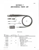
Страница 17: ...erio 1 Model No t Description Eff Disc y 1 2 3 4 5 6948 PROBE PACKAGE w termination 6949 PROBE PACKAGE w termination PROBE PACKAGE w termination 9 root probe probe package includes TERMINATION coaxial 6948 PROBE PACKAGE w accessories 6949 PROBE PACKAGE w accessories PROBE PACKAGE w accessories 9 foot probe probe package includes 6948 1 PROBE P6021 6949 1 PROBE P6021 1 PROBE P6201 9 foot 2 CLIP pro...

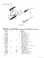
Страница 18: ...on y 1 2 3 4 5 PROBE P6021 PROBE P6021 PROBE P6021 9 foot probe includes 1 BODY probe top 1 BALL metal 0 094 inch OD 1 SLIDE ASSEMBLY upper shell 1 CONTACT electrical 1 T1 TRANSFORMER 1 SPRING helical compression 1 RETAINER return spring 1 HOLDER spring return 2 SCREW 2 56 x 1 4 inch RHS 1 BODY probe bottom 1 BODY probe bottom 1 BODY probe bottom 9 foot probe 1 HOLDER circuit board 6 SOCKET pin co...

Страница 19: ...TION Q Serial Model No Eff Disc Y 1 2 J 4 5 TERMINATION P6021 termination includes Description COVER termination top w knob CONNECTOR electrical BNC male FRAME termination CONNECTOR BNC female ASSEMBLY circuit board assembly includes INSULATOR plate BOARD circuit mounting hardware not included w assembly 2 SPACER sleeve 0 087 ID x 0 1 87 inch OD 2 WASHER fiat 0 090 ID x 0 188 inch OD 2 LOCKWASHER ...

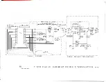
Страница 20: ... FORMER I I LI4 I 3T J R3b CoRE r 04 TI4 t P2 0 J 20 rl J R2ZJ n f f P39 LIO I I I I 1 _ 50M RIS 820 LI2 I I I I I I 5O u 1 4 CI3 2 I I I 1 ADDED AFTER 1 1 2 49 I C 50 C 2Z 5 25 L 31 t04 H R35 3 1 34 2 4 5 i III I I I II 5 ILLU L_____________L _____ _ I 1 I I I __ J 4 1 P o02 1 PROBE PG02 1 PA551VE TE RMINATIOt l I TYPE P60 2 J CURRENT PROBE TERMINATION 0670 R EV APR 1974 ...

Отзывы: