5.
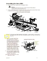
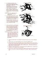
For Flange Mounted Motor Only.
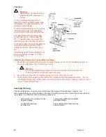
Screw the motor mount plate to the
motor using four flathead Allen screws
(M6x20 Metric or 3/8 x 1 for
USA/Canada). If the motor has an
integral on/off switch, make sure the
motor is oriented for access to the
switch.
L
Note: In the USA, the
Motor is sometimes supplied with the
lathe - the motor needs to be mounted
so that the switch is on the top for easy
access.
Flange Mounted Motor
Motor
Motor
Mount Plate
Flathead
Screws (4)
L
Note: The foot mounting rail kit is an
option not included with the
standard lathe.
6.
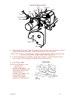
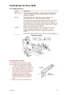
For Foot Mounted Motor Only. Screw
the mounting rails to the motor mount
plate using four M8 bolts and washers.
Then attach the motor to the rails using
four M8 bolts, nuts, and washers.
Adjust the position of the motor on the
rails after the pulley is attached (steps
7-10). Then tighten the bolts to firmly
secure the motor to the rails.
Foot Mounted Motor
Motor
Motor
Mount Plate
Bolts (4)
Rails
Bolts (4)
Foot
Mounting
Rail Kit
(optional)
7.
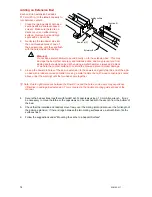
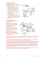
Fit the key into the motor shaft keyway.
Align the keyway in the motor pulley to
the motor shaft and slide the pulley
onto the motor shaft. Leave about 13
mm (1/2-inch) between the pulley and
motor. Loosely secure the pulley to
the shaft with a M8x10 set screw with
an Allen wrench.
L
Note:The motor pulley is available with a
5/8-inch bore (US, Canada) or a 19
mm bore (NZ, Australia, Europe,
South Africa). Make sure the motor
pulley bore is correct for the motor
shaft. (The 19 mm pulley has a ring
on the boss at the key end to aid
identification).
Installing the Motor Pulley
Set Screw
Key
Motor Shaft
Motor Pulley
Allen
Wrench
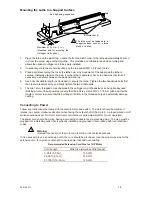
8. Place the extra M12 washer (not illustrated) supplied in the Flange kit over the rear Headstock
stud.
9. Place the motor mount plate with attached motor over both the Headstock studs.
10. Place the headstock guard on the headstock; part of it slips between the motor mount plate and
the motor pulley. The extra M12 washer mentioned in step 8 should be on the Flange side on the
guard. Attach the guard to the headstock with five M5x10 screws. Tighten the screws after the
guard has been correctly positioned.
11. Install a M12 washer and M12 Nyloc nut on the lower (pivoting) headstock stud. Tighten the nut
until the motor mount plate is secure, but movable.
12. Place the motor mount cam over the upper (cam) headstock stud. Install a M12 washer and M12
Nyloc nut. Tighten the nut until smooth sliding action is achieved. Screw the Teebar into the
cam.
12
92-0106-017


