Teka BKSSL BPM Скачать руководство пользователя страница 8

IMPORTANT SAFETY INFORMATION LISTED ON REVERSE

READ, FOLLOW, AND SAVE ALL SAFETY AND INSTALLATION INSTRUCTIONS

DATE

5-14-18

40429 Brickyard Drive • Madera, CA 93636 • USA

559.438.5800 • FAX 559.438.5900 

www.tekaillumination.com • [email protected]

REFERENCE NUMBER

INS-2569-03

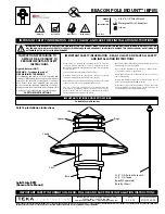
BEACON POLE MOUNT™ (BPM)

3.  Detach heatsink from fixture body via quick 

disconnect. Carefully pull away and turn upside 

down to access LED.


Do not pull on connector or wiring. Handle 

with care.

1.  Loosen three (3) captive #10-24 screws on cap 

with 5/32” Allen wrench. 

5.   Loosen two (2) #4-40 screws with 1/16” Allen 

wrench. 

4.   Loosen three (3) #6-32 set screws on side of 

dome lens optic holder using


1/16” Allen wrench. 

Gently remove dome lens and optic holder.

6.  Carefully remove LED module from heatsink. 


Do not pull on connector or wiring. Handle 

with care.


Fragile! Do not pull on connector or wiring. 

Handle with care.

7.  Use small pick tool to push connector off LED 

board through two small slots behind connector. 

Once loose, lift connector upwards and off board. 

NEEDED

FOR 

INSTALLATION:

By Others

5/32”, 3/32” & 1/16” Allen Wrench
Waterproof Wire Connectors
Gloves

2.   Loosen three (3) #4-40 screws with 3/32” Allen 

wrench that hold heatsink to fixture body.

8.  Spread thin, even layer of thermal paste on back 

of new LED module. Place new LED module onto 

heatsink, lining up module with holes for screws. 

Tighten two (2) #4-40 screws using 1/16” Allen 

wrench to secure LED module to heatsink. 

9.  Press connector straight downwards into slot 

on module to snap into place.


Connector will only fit in one direction.

Replacing Optic and LED Module

 LED Replacement Installation Instructions

Содержание BKSSL BPM

Страница 1: ...uctions Qualified Personnel with appropriate personal protective equipment must perform all servicing of this product Before wiring to power supply and during servicing turn off and lock out power at fuse or circuit breaker before service The use of accessory equipment not recommended by the manufacturer or installed contrary to instructions may cause an unsafe condition The use of damaged compone...

Страница 2: ...imming controls to top of pole Feed through strain relief LINE Red FIXTURE COM Driver Black GROUND DIM DIM GROUND IN HOUSING LINE Red FIXTURE COM Driver Black DIM DIM GROUND ON PLATE LINE Red FIXTURE COM Driver Black DIM DIM 3 Place connections and driver on bracket into pole Rest bracket on pole top or tenon Phase 1 Install Pole 1 Install 3 1 2 O D pole By Others or pole with 3 1 2 O D tenon By O...

Страница 3: ...ructions Qualified Personnel with appropriate personal protective equipment must perform all servicing of this product Before wiring to power supply and during servicing turn off and lock out power at fuse or circuit breaker before service The use of accessory equipment not recommended by the manufacturer or installed contrary to instructions may cause an unsafe condition The use of damaged compon...

Страница 4: ...ing dimming controls to driver primary side dimming controls Connect secondary side of driver to wiring for fixture leads See wiring diagram WIRING DIAGRAM Phase 2 Fixture Installation Hinge Base Option LINE Red FIXTURE COM Driver Black GROUND DIM DIM GROUND IN HOUSING LINE Red FIXTURE COM Driver Black DIM DIM GROUND ON PLA LINE COM DIM DIM 2 Hinge pole open for access to conduit and branch circui...

Страница 5: ...tekaillumination com REFERENCE NUMBER INS 2569 01 BEACON POLE MOUNT BPM Hinge Base Installation Instructions 7 Make watertight connections using waterproof wire connectors to connect fixture leads to secondary leads from driver Leave length for future service See wiring diagram 8 Slide fixture over pole top Secure with four 4 1 4 20 screws using 1 8 Allen wrench Make sure the fixture is completely...

Страница 6: ...ions Qualified Personnel with appropriate personal protective equipment must perform all servicing of this product Before wiring to power supply and during servicing turn off and lock out power at fuse or circuit breaker before service The use of accessory equipment not recommended by the manufacturer or installed contrary to instructions may cause an unsafe condition The use of damaged components...

Страница 7: ...op 1 Thread fixture leads down pole to splice location at hand hole 2 Slide fixture over pole top Secure with four 4 1 4 20 set screws using 3 16 Allen wrench Make sure the fixture is completely seated Do not overtighten Hand Hole Installation Instructions 4 Make watertight connections from primary branch circuit to driver leads using waterproof wire connectors By Others Connect green ground wire ...

Страница 8: ... holder 6 Carefully remove LED module from heatsink Do not pull on connector or wiring Handle with care Fragile Do not pull on connector or wiring Handle with care 7 Use small pick tool to push connector off LED board through two small slots behind connector Once loose lift connector upwards and off board NEEDED FOR INSTALLATION By Others 5 32 3 32 1 16 Allen Wrench Waterproof Wire Connectors Glov...

Страница 9: ... com REFERENCE NUMBER INS 2569 03 BEACON POLE MOUNT BPM 11 Attach heatsink to fixture body via quick disconnect Line up on spacers 13 Attach cap with securing three 3 10 24 screws using 5 32 Allen wrench 10 Place dome lens into optic holder Tighten three 3 6 32 set screws on side of dome lens optic holder using 1 16 Allen wrench Relamping Instructions 12 Tighten three 3 4 40 screws with 3 32 Allen...

Отзывы: