


1592006207 XB570L GB r1.1 26.08.2015
XB570L
4 /20
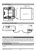
•
Each instrument is provided with an output for remote display XR REP, which shows the temperature of
cabinets or goods.
•
The XB570L controller is provided with internal real time clock and can be connected to the XB07PR
printer. This means that a report, which includes all the main features of cycle, can be printed: start and
end of the cycle, length of the cycle, logging of the temperature of the cabinet and goods.
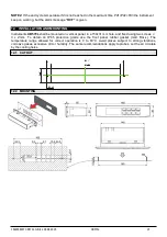
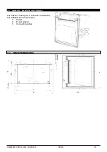
4. MOUNTING & INSTALLATION
Model XB570L is a controller for panel mounting: the cut out dimensions are 150x31 mm and it has to be
fixed with screws. The ambient operating temperature range is from 0.0 to 60°C. Avoid locations subject to
heavy vibration, corrosive gases or excessive dirt. The same warnings have to be applied to the probes.
Ensure enought ventilation around the instrument.
5. ELECTRICAL CONNECTIONS
The instruments are provided with a screw terminal block to connect cables with a cross section up to
2.5mm
2
for probes and digital input.
Spade on 6.3 mm heat-resistant wiring for supply and loads. Before connecting cables make sure the power
supply complies with the instrument’s requirements. Separate the input connection cables from the power
supply cables, from the outputs and the power connections.
Do not exceed the maximum current allowed
on each relay
, in case of heavier loads, a suitable external relay has to be used.
The probes shall be mounted with the bulb upwards to prevent damages due to casual liquid infiltration. It is
recommended to place the thermostat probe away from air streams to correctly measure the average room
temperature. Place the defrost termination probe among the evaporator fins in the coldest place, where most
ice is formed, far from heaters and from the warmest place during defrost, to prevent premature defrost
termination.
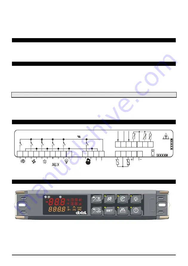
6. CONNECTIONS
oA2
oA1 oA3
7. FRONTAL PANEL
5.1 PROBES CONNECTION
Doo
r
Co
mm
on
Co
nf.
In
p.
De
f
R
oo
m
In
se
rt
1
HO
T
KE
Y
1 2 3 4 5 6 7 8
16A
8A
8A
8A
16A
250V
~
250V
~
250V
~
250V
~
250V
~
20A 250V
16FLA(96LRA)
MAX
20A
25 26 27 28 29 30 31
9 10
Def
Light
11 12 13 14
N Line
Supply
Comp
115V
~
17 18 19 20 21
Remote
Display
PRINTER
Alarm
Fan
RS 485
In
ser
t 3
In
se
rt
2
Содержание BLC10
Страница 1: ...BLAST CHILLER FREEZER User Manual PT SL 49 61 EN FR IT ES 3 13 25 37...
Страница 2: ...2...
Страница 9: ...9 QUICK GUIDE For the daily use...
Страница 13: ...REFROIDISSEURS CONG LATEURS RAPIDES Manuel d utilisation PT SL 49 61 FR IT ES 13 25 37...
Страница 14: ...14...
Страница 21: ...21 GUIDE RAPIDE Guide rapide quotidien...
Страница 25: ...ABBATTITORI CONGELATORI Manuale d uso PT SL 49 61 IT ES 25 37...
Страница 26: ...26...
Страница 33: ...33 33 GUIDA RAPIDA Guida pratica quotidiana...
Страница 37: ...ABATIDORES CONGELADORES Manual del usuario PT SL 49 61 ES 37...
Страница 38: ...38...
Страница 45: ...45 GU A R PIDA Gu a r pida diaria...
Страница 49: ...PT SL 49 61 ABATEDORES DE TEMPERATURA CONGELADORES Manual do utilizador...
Страница 50: ...50...
Страница 57: ...57 GUIA R PIDO Guia r pido di rio...
Страница 61: ...SL 61 HLADILNIK ZAMRZOVALNIKA ZA HITRO HLAJENJE ZAMRZOVANJE Navodila za uporabo...
Страница 62: ...62...
Страница 69: ...69 HITRI VODNIK Za dnevno uporabo...
Страница 73: ...1592006207 XB570L GB r1 1 26 08 2015 XB570L 2 20 XB590L XB570L...
Страница 94: ...1593006207 XB570L FR r1 0 26 08 2015 XB570L 2 24 XB590L XB570L...
Страница 118: ...1591006207 XB570L IT r1 1 26 08 2015 XB570L 2 24 XB590L XB570L...
Страница 141: ...1591006207 XB570L IT r1 1 26 08 2015 XB570L 25 24...
Страница 142: ...1594006207 XB570L SP r1 0 26 08 2015 XB570L 2 20 XB590L XB570L...
Страница 162: ...XB590L XB570L...
Страница 177: ...1592006207 XB570L GB r1 1 26 08 2015 XB570L 16 20 3 12 2 MONTAGEM...
Страница 184: ...1592006207 XB570L GB r1 1 26 08 2015 XB570L 2 20 XB590L XB570L...