teel 2P899A Скачать руководство пользователя страница 11

Maintenance (Continued)

2. Follow steps 1 through 5 under

“Cleaning/Replacing Impeller.”

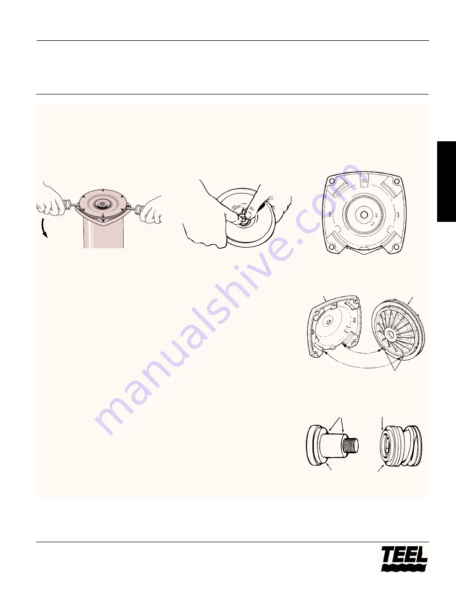
3. Remove rotating half of seal by

placing two screwdrivers under seal
plate and carefully prying up (Figure
15). Seal plate will slide off shaft,
bringing seal with it.

IMPORTANT:

Be sure you do not

scratch or mar shaft; if shaft is marred,
it must be dressed smooth with fine
emery or crocus cloth before installing
new seal. DO NOT reduce shaft
diameter.
4. Place seal plate face down on flat

surface and tap out stationary half
of seal.

IMPORTANT:

Be sure you tap on the

ceramic seat, not on copper heat sink.
Do not disturb heat sink (Ref. No. 4,
Figure 29).

INSTALLING NEW SEAL 

1. Clean seal cavity in copper heat sink.

Do not disturb heat sink. (If heat
sink is moved or dislodged, see
instructions for “Copper Heat Sink
Installation,” Page 12.

2. Wet outer edge of O-Ring on

ceramic seat with liquid soap. Be
sparing!

3. Put clean cardboard washer on seal

face. Polished face of ceramic seat

should be up. With thumb pressure,
press ceramic seal half firmly and
squarely into seal cavity in copper
heat sink (See Figure 16). If seal will
not seat correctly, remove, placing
seal face up on bench. Reclean
cavity. Seal should now seat
correctly.

4. If seal does not seat correctly after

recleaning cavity, place a cardboard
washer over polished seal face and
carefully press into place using a
piece of standard 3/4” pipe as a
press.

IMPORTANT:

Be sure you do not

scratch seal face.
5. Dispose of cardboard washer and

recheck seal face to be sure it is free
of dirt, foreign particles, scratches,
and grease.

6. Inspect shaft to be sure it is free of

nicks and scratches.

7. Reassemble seal plate to motor

flange. BE SURE it is right side up:
index pins should be down; seal
plate is marked at top (See Figures
17 and 18).

8. Apply liquid soap sparingly (one

drop is sufficient) to inside diameter
of rotating seal member.

9. Slide rotating seal member (carbon 

face first) onto shaft until rubber
drive ring hits shaft shoulder.

IMPORTANT:

Be sure not to nick or

scratch carbon face of seal when
passing it over threaded shaft end and
shaft shoulder (See Figure 19). The
carbon surface must remain clean or
short seal life will result.

Models 3P683D, 3P684D, 2P899A and 3P715B

11

Teel Operating Instructions and Parts Manual

®

E

N
G

L

I

S

H

506 0194

Figure 15 – Pry Off Seal PLate

Figure 16 – Press In Seal

Figure 17 – Locate Seal Plate on Motor
Flange

Top of motor flange

Seal plate index pins slide in here

Figure 19 – Do Not Nick Seal On Shaft
Shoulder

Figure 18 – Locate Seal Plate On Motor
Flange

Motor flange

Seal plate

Index pins

Ceramic face

Be careful that
shaft shoulder. . . . . does not damage

seal faces

Carbon face

Содержание 2P899A

Страница 1: ...a 6 gallon pre charged tank equal to a fifteen gallon standard tank Used with drilled cased driven point or dug wells or in cisterns or lakes Comes assembled to save on installation Equipped with a 11...

Страница 2: ...ound motor before connecting to power supply Meet United States National Electri cal Code Canadian Electrical Code and local codes for all wiring Follow wiring instructions in this manual when connect...

Страница 3: ...cept as provided below no warranty or affirmation of fact expressed or implied other than as stated in the LIMITED WARRANTY above is made or authorized by Dayton PRODUCT SUITABILITY Many jurisdictions...

Страница 4: ...ould be at least as large as the suction port on the pump include a check valve See Figure 1 Support the pipe so that there are no dips or sags in the pipe so it doesn t strain the pump body and so th...

Страница 5: ...est possible fittings especially elbows in the suction pipe The suction pipe should be at least as large as the suction port on the pump 2 Assemble a foot valve and suction pipe See Figure 3 Make sure...

Страница 6: ...ove the 1 8 NPT pipe plug from the pump Air Volume Control AVC port See Figure 5 Run tubing from the pump s AVC port See Figure 5 to the port on the AVC mounted on the tank See instructions provided w...

Страница 7: ...Manual E N G L I S H Figure 7 Motor wiring connections through Pressure Switch Match motor voltage to line voltage A B L2 L1 A B L2 L1 A B L2 L1 A B L2 L1 230 Volt to 115 Volt Conversion Spade Connect...

Страница 8: ...authority NOTE If you are connecting the motor to a 230 volt circuit using a four conductor cable connect both the neutral white and ground green to the ground terminal The other two wires two black w...

Страница 9: ...Run the pump through one or two complete cycles to verify correct operation This will also help clean the system of dirt and scale dislodged during installation Maintenance Pump and piping need not b...

Страница 10: ...haft flats and unscrew impeller by turning counterclockwise when looking into eye of impeller 5 To reinstall reverse steps 1 through 4 Mount diffuser as shown in Figure 20 6 See directions under Pump...

Страница 11: ...seat correctly after recleaning cavity place a cardboard washer over polished seal face and carefully press into place using a piece of standard 3 4 pipe as a press IMPORTANT Be sure you do not scrat...

Страница 12: ...8 washer pull heat sink into cavity See Figure 22 5 Clean out any surplus Permatex from insert cavity where new seal will be located Figure 23 6 Follow steps 2 through 11 under Installing New Seal PU...

Страница 13: ...nnect power to pump 2 Follow steps 2 through 5 under Testing For Bladder Leakage above 3 Remove nuts from tank cover flange Tap cover flange to break seal and remove 4 Bladder will not come out in one...

Страница 14: ...tire gauge Air pressure should be 2 psi below pump pressure switch cut in setting 3 If the air pressure is more than 2 psi below the cut in setting add air to the tank Use an air compressor or a porta...

Страница 15: ...ed Pipe plug 1 14 1 4 NPT w TFE Barbed elbow 2 15 Switch tube U37 191P 1 16 Plastic gasket J20 18 1 17 Pump ejector body insert N76 29P 1 18 10 16 Hi Lo Capscrew U30 742SS 4 19 45 Nozzle N34P 19 1 20...

Страница 16: ...list Address parts correspondence to Grainger Parts P O Box 3074 1657 Shermer Road Northbrook IL 60065 3074 U S A 1 Tank Assembly Incl Diaphragm Valve Nuts Inlet Flange U231 498 1 2 Inlet Flange Assem...

Страница 17: ...er level in a shallow well operation exceeds 25 ft a deep well pump is needed 3 Ejector or impeller is plugged 3 Clean ejector or impeller see maintenance 4 Check or foot valves stuck in closed 4 Repl...

Страница 18: ...f necessary add air pressure with an air hose Check air valve for leaks using a soapy solution and replace core if necessary Air spurts from 1 Pump is picking up prime 1 As soon as pump picks up prime...

Отзывы: