57
98-05141 R2
www.teejet.com
CHAPTER 5 – APPENDIX
APPENDIX A - ICON REFERENCE
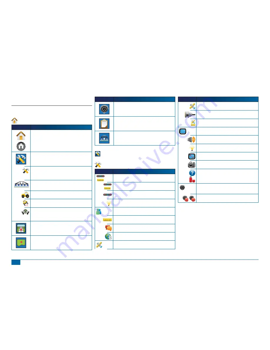
Menu Options
Icon
Description
Home – Displays Menu Options including Unit Setup, Vehicle
View, Field View, RealView Guidance, Job View and Boom
Monitoring.
Unit Setup – Allows System, BoomPilot/Single Boom,
Vehicle, Tilt Correction and FieldPilot setups.
System Setup. Sets options for lightbar, culture (units,
language & time zone), GPS, console (volume, display
brightness, touch screen calibration, screenshot & about/save)
and video cameras.
BoomPilot/Single Boom Setup. Sets swath overlap, delay on/
off, number of boom sections and associated boom section
widths.
Vehicle Setup. Sets vehicle type, antenna height, boom
direction and boom distance from antenna.
Tilt Gyro Module Setup. Sets on/off and calibrates tilt
correction.
FieldPilot Setup. Sets autosteer on/off, options for valve
setup (frequency and minimum & maximum duty cycles),
valve testing and FieldPilot con
fi
guration (coarse steering
adjustment,
fi
ne steering adjustment, deadband & look ahead).
Vehicle View – Allows a computer-generated image of
the vehicle position displayed in the application area.
Access options for guidance modes, boundary areas
and BoomPilot.
Field View – Allows a computer-generated image of
the vehicle position and application area from an aerial
perspective. Access options for boundary areas and
marked point. Enter World View and Pan modes.
Icon
Description
RealView Guidance – Allows a single live video input
or a set of four live inputs to be displayed instead of a
computer-generated image. Enter guidance over video
and steering angle modes.
Job View – Allows saving of information to a USB drive
or clearing of information from unit.
Boom Monitoring – Allows a computer generated
view of active/inactive boom sections. Enable/disable
BoomPilot.
Unit Setup
System Setup
Icon
Description
Lightbar Setup – LED Spacing, Display Mode and LED
Brightness.
LED Spacing. Sets the distance illustrated by the illuminated
LEDs.
Display Mode. Determines whether the lightbar represents the
swath position or vehicle position.
LED Brightness. Adjusts brightness of the lightbar LEDs.
Culture Setup – Units, Language and Time Zone.
Units. De
fi
nes the system measurements.
Language. De
fi
nes the system language.
Time Zone. Establishes the local time zone.
GPS Setup – GPS Type, GPS Port and GPS Status
Information
Icon
Description
GPS Type. Customizes system to accept GPS, DGPS, or either
type of signal.
GPS Port. Sets COM port transmission to Internal or External.
GPS Status. Displays information regarding data rates, number
of satellites in view, and satellite quality and ID.
Console Setup – Volume, LCD Brightness, Touch-screen
Calibration, Screenshot and About/Save.
Volume. Adjusts volume level of audio speaker.
LCD Brightness. Adjusts brightness of the console display.
Touch Screen Calibration. Used to initiate a touch screen
calibration.
Screenshot. Allows screen images to be saved to a USB drive.
About. Displays information regarding system software as well
as the software versions of modules connected to the CAN bus.
Save. Saves console setup data to a USB drive.
Video Setup. Used to confi gure up to 8 cameras with
the use of a Video Selection Module. Gray = VSM
unavailable.
A
B
Cameras. Con
fi
gure cameras to normal, reverse, upside down
or reverse upside down.


