3
www.teejet.com
DynaJet
®
Flex
CAN Start Terminator
(female)
at Boom Section 1
DynaJet Solenoids
to CAN connection
DynaJet Solenoids
Power Distribution Module
Nozzle Harness
DynaJet Driver
DynaJet Solenoids
DynaJet Solenoids
Nozzle Harness
DynaJet Driver
DynaJet Solenoids
DynaJet Solenoids
Nozzle Harness
DynaJet Driver
DynaJet Solenoids
DynaJet Solenoids
Nozzle Harness
DynaJet Driver
INSTALLATION – STANDARD MODE
DynaJet® drivers
There will be one DynaJet driver 78-05122 per boom section with a
limit of 20 nozzles per section.
• Mount them so they are at the end of each section that is
closest to the middle of the boom.
Power
Power will be sourced from the battery using the 60 amp fused cable
45-05943.
Power from the battery will be routed to the boom using the 6 gauge
power cables 45-05942-xx
The power distribution modules 78-05121-xx will connect to the
45-05942-xx cables.
Power will then route from 78-05121-xx to each DynaJet driver
78-05122 using cables 45-05971-xx.
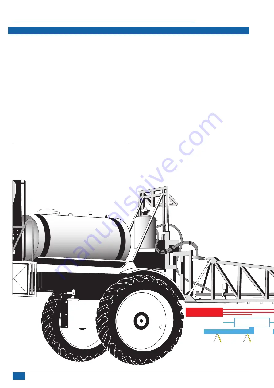
Figure 2: Installation diagram - standard mode
Nozzle harnesses
When installing nozzle harnesses 45-05935-xx-xx always start with
section 1 and continue to the last section.
Each section will require nozzle harnesses designed for your specific
nozzle spacing and number of nozzles.
• Nozzle harnesses are built with an even number of outputs.
•
Some sections will use more than one harness to equal the
number of nozzles in that section.
The yellow and white solenoid cables on the nozzle harnesses must
alternate across the entire boom. When sections have odd numbers
of nozzles then accounting for the altering can be accomplished
one of two ways:
A. By crossing the two solenoid cables
B. By installing nozzle harness reversing adapters 45-05952
Содержание DynaJet Flex 7120
Страница 23: ......


