26
NT935BH
1.
Cable 20 x AWG 20/19 Cu/Sn
2.
Section 0.55 mm²
3.
Flame-protection insulation PVC105
4.
Standards CEI 20.35 IEC 332.1
5.
Maximum operating temperature: 90°C
6.
Configuration: 4 triples of three twisted and coloured conductors
7.
Screen on Cu/Sn
8.
Fireproof PVC sheath
9.
Outer diameter 12 mm
10.
Standard configuration in 100 m coils
TECHNICAL SPECIFICATIONS OF THE EXTENSION CABLE
FOR Pt100
The NT935 control unit has the selection n.o (normally open contact)/n.c (normally closed contact) for the ALARM, TRIP
and FAULT relays, programming steps from 30 to 35 page 14. Selecting the YES/NO setting introduces the Fail Safe and
No Fail Safe functions.
ALARM AND TRIP
By setting NO (NO Fail safe) the normally open contacts are in positions 5-7 Alarm and 8-10 Trip, they switch only when
the pre-set temperature limits are reached.
By setting YES (Fail safe), the normally closed contacts are in positions 5-7 Alarm and 8-10 Trip, they switch only when the
pre-set temperature limits are reached or as a result of no voltage.
FAULT
By setting YES (Fail safe), contact 11-12 is positioned as normally open, switches (closed) when a fault condition is
identified; see paragraph on alarms and ventilation on page 12.
Setting NO (NO Fail safe) the contact 11-12 is positioned as normally closed, switches (open) when a fault condition is
identified; see paragraph on alarms and ventilation on page 12.
If the fail safe function is disabled on the fault contact, the control unit will no longer be able to signal the fault due to power
failure. In this case it is advisable to enable the Fail safe on the ALARM contact for the afore-mentioned indication.
NOTE: NOTE: when the control unit is in one of the modes indicated below, it does not perform any thermal monitoring,
moreover the relays will all be disabled
the FAULT led will flash.
• Vis. display programming.
• PRG programming.
• Test of the relays.
The FAIL SAFE function is temporarily disabled and the FAULT relay switches.
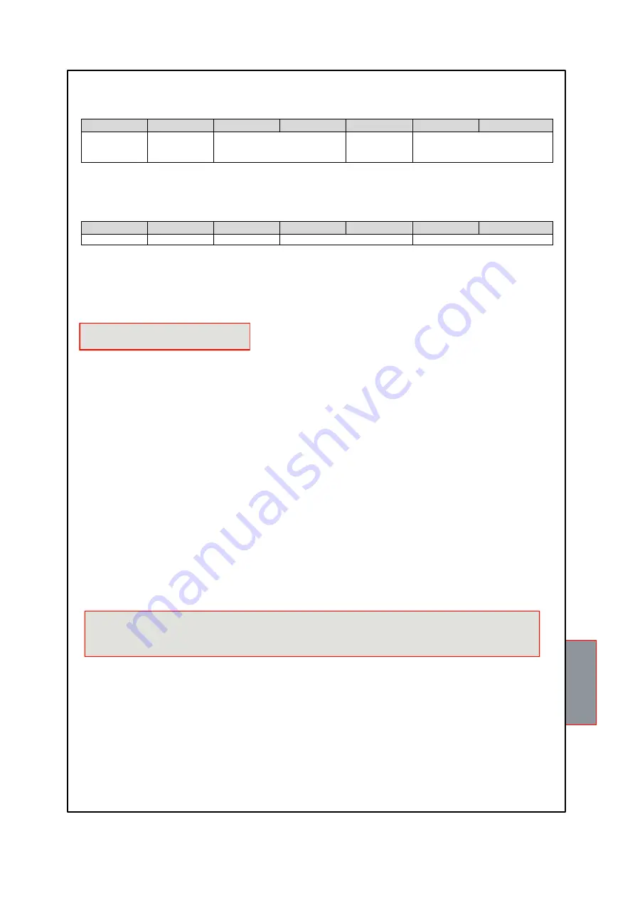
BARS/FANS STRUCTURE
BIT 7
BIT 6
BIT 5
BIT 4
BIT 3
BIT 2
BIT 1
--
Num. Bars 1;2
--
Num. Motors for bar 1; 2; 3
Bar programming TRBH Bit 5-4: 0 1=BAR1
1 0=BAR1-2
Programming of motors TRBH Bit 0-1: 0 1 = M1
1 0 = M1-M2
1 1 = M1-M2-M3
TRBH MOTOR STATUS
BIT 7
BIT 6
BIT 5
BIT 4
BIT 3
BIT 2
BIT 1
--
--
--
Motor status Bar_2
Motor status Bar_1
TRBH motor status: 00=OK
01=general motor fault
10=overtemperature
11= communication failure with the control box/bar
FAIL SAFE FUNCTION


