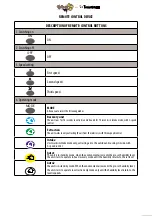
Tecnosystemi PICO HP2 Series Скачать руководство пользователя страница 3

Issue

When switching 

on the unit, its fan 

does not start.

After powering 

on, circuit breaker 

triggers stop.

Poor air flow

Possible causes

Power supply.

Check that the unit is correctly connected 

to the mains, and make any adjustments 

necessary.

Turn off the unit. Solving the engine block 

and fan clogging. Clean the blades. Restart 

the unit.

Switch off the unit. Contact customer 

service.

Set to higher speed.

Clean or replace the filter, clean the fan 

and regenerator. For regenerator and filter 

maintenance, see page 18.

The motor is blocked, the impeller is 

clogged.

Excess voltage from electrical short-circuit.

Speed set to "slow".

Dirty filter, fan or exchanger.

Fault management 

TROUBLESHOOTING

Read the user's manual carefully before using and installing the single-chamber reversible-flow 

ventilation unit with energy recovery, referred to below as "ventilation unit" or "unit". 

The installation and operation of this unit must be carried out in accordance with the user's manual, 

and the provisions of applicable local and national laws and applicable technical and electrical 

standards.   The warnings in the user manual must be considered carefully as they contain information 

that is vital for personal safety. 

Failure to follow the safety instructions can cause injury or damage to the ventilation unit. 

Read the manual carefully and keep it for as long as you use the ventilation unit. 

When transferring the command of the unit, the user manual must be handed over to the receiving 

user. Symbols used in the manual:
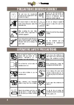
SAFETY REQUIREMENTS

3

Содержание PICO HP2 Series

Страница 1: ...HP2 30 HP2 55 HP2 80 WALL INSTALLED REVERSIBLE FLOWVENTILATION UNIT WITH HEAT RECOVERY AND REMOTE CONTROL USER MANUAL Vers 02 29 01 2016...

Страница 2: ...ted for continuous operation always connected to power mains The transported air must not contain flammable or explosive mixtures chemical vapours coarse dust soot and oil particles sticky substances...

Страница 3: ...management TROUBLESHOOTING Read the user s manual carefully before using and installing the single chamber reversible flow ventilation unit with energy recovery referred to below as ventilation unit...

Страница 4: ...e power cable Do not damage the power cable OPERATIVE SAFETY PRECAUTIONS Do not touch the controls or remote control with wet hands Do not perform maintenance on the ventilation unit with wet hands Do...

Страница 5: ...CAPACITY m h 26 28 5 32 40 45 50 65 72 80 RPM min 1 1863 2070 2300 2106 2340 2600 2754 3060 3400 SOUND PRESSURE AT 1m dB A 17 19 21 21 23 25 24 26 28 ACOUSTIC PRESSURE AT 3 m dB A 15 17 19 19 21 23 22...

Страница 6: ...t exchanger uses the heat energy in the extracted air to heat the incoming air flow The exchanger is equipped with a pull cord inside to facilitate its extraction from the ventilator The heat exchange...

Страница 7: ...NSIDE WITH 3 SPEED CONTROL THE UNIT IS IN STAND BY MODE THE UNIT IS IN STAND BY MODE WHEN THE ENVIRONMENT AIR EXCEEDS THE PRE SET HUMIDITY LEVEL THE UNIT STARTS TO OPERATE IN HEAT RECOVERY MODE UNTIL...

Страница 8: ...is shown in the figure below WARNING THE VENTILATION UNIT MUST NOT BE INSTALLED WHERE THE AIR DUCT CAN BE BLOCKED BY SHUTTERS BLINDS ETC TO PREVENT DUST DEPOSITING AND ACCUMULATING ALSO CURTAINS MAY B...

Страница 9: ...iagram on page 12 Prepare the four mounting holes and secure the mounting plate onto the part with four 4x40 screws and four raw plugs 6x40 included Align the air duct with respect to the mounting pla...

Страница 10: ...air duct 6 Fit the ventilation unit onto the mounting plate 6 Fit the ventilation unit onto the mounting plate 1 Mark the fixing holes for the external ventilation grid and drill them For convenience...

Страница 11: ...the holes 3 Now remove the external grid to allow access to the fixing holes Remove the upper part of the external ventilation grid 4 Secure the back of the grid to the wall with the 4x40 screws incl...

Страница 12: ...nnect the output contact of the first unit to the outlet of the input contact of the second one Now connect the second unit to the third unit in the same way up to 10 ventilation units can be connecte...

Страница 13: ...m the interiors with 3 speed control Auto 1 The unit is in stand by mode when the environment air exceeds the pre set humidity level the unit starts to operate in heat recovery mode until the humidity...

Страница 14: ...tracting the air from the interiors with three speed control Intake Unit works in intake mode only extracting air to the outside and sucking it inside with 3 speed control Auto1 The unit is in stand b...

Страница 15: ...WALL MOUNTED STATIC EXTRACTION UNITWITH MECHANICAL CROSS FLOW AND HEAT RECOVERY USER MANUAL Vers 01 29 01 2016 100...

Страница 16: ...h 75 87 93 RPM min 1 2754 3060 3400 SOUND PRESSURE AT 1m dB A 31 33 35 ACOUSTIC PRESSURE AT 3 m dB A 29 31 33 MAX AIRTEMPERATURE C FROM 10 CTO 50 C REGENERATOR EFFICIENCY 95 EXCHANGE BOX MATERIAL POL...

Страница 17: ...of operation The high efficiency polyester cross flow exchanger exploits thermal energy of the air extracted from outside to warm up the air inside The heat exchanger is installed on an insulating mat...

Страница 18: ...UCKING IT INSIDE WITH 3 SPEED CONTROL THE UNIT IS IN STAND BY MODE WHEN THE ENVIRONMENT AIR EXCEEDS THE PRE SET HUMIDITY LEVEL THE UNIT STARTS TO OPERATE IN HEAT RECOVERY MODE UNTIL THE HUMIDITY RETUR...

Страница 19: ...on page 12 Prepare the four mounting holes and secure the mounting plate onto the part with four 4x40 screws and four raw plugs 6x40 included Align the air duct with respect to the mounting plate now...

Страница 20: ...Insert the filter the ceramic exchanger and another filter in consecutive order into the air duct 6 Fit the ventilation unit onto the mounting plate 6 Fit the ventilation unit onto the mounting plate...

Страница 21: ...s Remove the upper part of the external ventilation grid 4 Secure the back of the grid to the wall with the 4x40 screws included 5 Fit the upper part of the grid 21 1 Mark the fixing holes for the ext...

Страница 22: ...ventilation units in series connect the socket of the mounting plate output contact of the first ventilation unit with the outlet of the input contact of the second plate of the ventilation unit asse...

Страница 23: ...he air from the interiors with three speed control Auto 1 the unit is in stand by mode When the environment air exceeds the pre set humidity level the unit starts to operate in heat recovery mode to r...

Страница 24: ...nly extracting the air from the interiors with three speed adjustment Intake Unit works in intake mode only extracting air to the outsideand sucking it inside with 3 speed control Auto1 the unit is in...

Страница 25: ...of its filters 1 Fan maintenance once a year Pull on the ventilation unit to remove Clean the impeller blades To dust use a soft brush cloth or vacuum cleaner Do not use water abrasive cleaners solven...

Страница 26: ...ion of the filter is approximately three years Contact the seller for replacement filters Even technical maintenance cannot completely prevent the accumulation of dirt on the regenerator unit Have the...

Страница 27: ...nd maintenance non observance of the product s technical specifications repairs or modifications carried out by the client or by third parties without the supplier s prior written authorization lack o...

Отзывы: