13
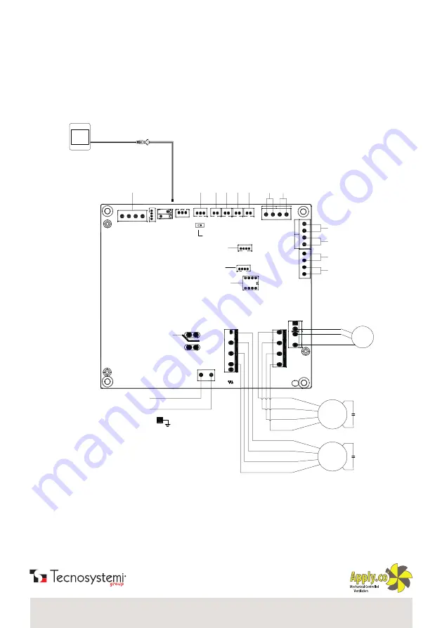
Ingresso segnale allarme antincendio
Uscita segnale guasto
Uscita segnale
funzionamento
94V0
PO
RT
4
PO
RT
3
P
O
R
T
2
P
O
R
T
1
L
N
12V
A
GN
D
B
AN2
AN1
AN3
AN4
COMM1S1
S2
*
*
C02
*
C
N
10
CN8
CN12
C
N
11
CN9
CM-DM
CN-SAFM
CN-EAFM
LD4
LD3
CN13
CN3
CN7
CN6
CN4
CN5
CN2
SW4
CN27
L
N
Connect with
heater or relay
By-pass switch
Fire alarm signal input
Fault signal output
Running signal output
E
xt
er
na
l s
w
ith
S
A
te
m
p.
FR
(E
A
) t
em
p.
O
A
te
m
p.
R
A
te
m
p.
C
O
2
se
ns
or
R
es
er
ve
s
w
itc
h
R
S
48
5
po
rts
Humidity sensor
Dial switch
M1
M2
Yellow
Blue
White
Black
Yellow
Blue
White
Black
Exhaust fan
Supply fan
Voltage:220V-1ph-50/60Hz
PE
WD20220063
WIFI
WIFI ports
GM
Yellow
White
Black
By-pass
Control panel
Joint of control panel and cable
Standard length: 5m
Connect the tin end of cable
to the port, no sequence
NO
ON to use touch screen panel in 4 wiring
OFF to use 2 or 3 wiring panel.
/ WIRING DIAGRAMS
Содержание HI-TECH PUR 12300012
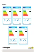
Страница 26: ...26 ECOLABEL...
Страница 28: ...28 NOTE NOTES...
Страница 29: ...29 NOTE NOTES...
Страница 30: ...30 NOTE NOTES...
Страница 31: ...31 NOTE NOTES...


