


26
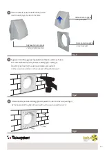
Collegare il secondo recuperatore con il terzo recuperatore nello stesso modo , ecc fino a 4 recuperatori possono
essere collegati in serie. L’operazione di collegamento in serie dei recuperatori deve avvenire con le apparecchiature
scollegate dalla rete elettrica.
IN
OUT
fig.6
PER RECUPERATORE
/ FOR RECOVERY UNIT
PICO HP2 80 - HP2 100
5 m
5 m
5 m
PER RECUPERATORE
/ FOR RECOVERY UNIT
PICO HP2 55 - 30
ALIMENTAZIONE ESTERNA IN DOTAZIONE PER
I CODICI
/ EXTERNAL POWER SUPPLY
INCLUDED
WITH PART NUMBERS
:
ACD100001 - ACD100002 - ACD100003
ACD100007 - ACD100008 - ACD100009
ACD100013 - ACD100014 - ACD100015
ACD100046 - ACD100048 - ACD100050
ALIMENTAZIONE AD INCASSO IN DOTAZIONE
PER I CODICI
/ BUILT-IN POWER SUPPLY
INCLUDED
FOR PART NUMBERS
:
ACD100004 - ACD100005 - ACD100006
ACD100010 - ACD100011 - ACD100012
ACD100016 - ACD100017 - ACD100018
ACD100047 - ACD100049 - ACD100051
Connect the second recovery unit to the third recovery unit in the same way and so on, allowing up to 4 recovery units to
be connected in series. Connecting the recovery units in series must be performed with the devices disconnected from the
mains supply.
CONNECTION OF RECOVERY UNITS IN SERIES
When the recovery units are connected in series, all the connected recovery units are controlled by the first recovery unit and
a single remote control. In order to connect the recovery units in series, connect the exit contact press of the first recovery unit
(identified with the OUT word) to the entry contact press of the second recovery unit (identified with the IN word).
SCHEMA DI INSTALLAZIONE A CASCATA MAX 4 PICO
/ INSTALLATION DIAGRAM FOR MAX 4 “PICO WI” UNITS IN CASCADE
ALIMENTATORE NON IN DOTAZIONE
/ POWER SUPPLY NOT INCLUDED
ALIMENTATORE NON IN DOTAZIONE
/ POWER SUPPLY NOT INCLUDED