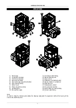


INSTALLATION AND SETTING INSTRUCTIONS
- 23 -
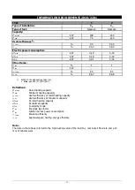
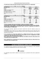
The table below shows indicative information about the gas burner pre-adjustment:
Functioning of the burner at its
MAX.
nominal thermal
IMPUT
:
DESCRIPTION
UNIT
TYPE 1
TYPE 2
Brand
RIELLO
RIELLO
Model
mod
BS 3/M
RS 34/M MZ
Position of combustion head
notch
2
1
Position of air shutter
notch
65
80
G20 methane gas (when supplied)
mbar
20
20
Gas pressure to the hose
mbar
7,4
7,0
CO2
%
10
10
Functioning of the burner at its
MIN.
nominal thermal
IMPUT
:
DESCRIPTION
UNIT
TYPE 1
TYPE 2
Brand
RIELLO
RIELLO
Model
mod
BS 3/M
RS 34/M MZ
Position of combustion head
notch
2
1
Position of air shutter
notch
15
20
G20 methane gas (when supplied)
mbar
20
20
Gas pressure to the hose
mbar
1,8
0,8
CO2
%
10
10
THE PRE-CALIBRATION VALUES ARE MERELY INDICATIVE AND NOT BINDING.
THE BURNER MUST BE CAREFULLY CHECKED AND ADJUSTED DURING FIRST START-UP PHASE.
BESIDES, THE COMBUSTION AIR PRESSURE SWITCH MUST BE CALIBRATED, IN ORDER TO
AVOID UNHEALTHY COMBUSTION.
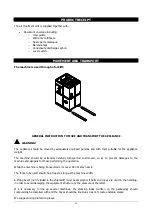
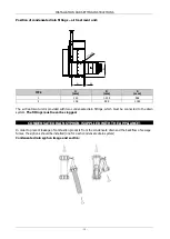
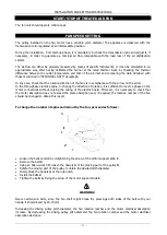
The gas burner assembly, adjustment, and electric connectio
n fall within the installer’
s province and
responsibility.
Said operations must be carried out only by skilled and competent technical personnel who perform the work
by scrupulously adhering to the instructions mentioned in the burner and supply ramp manuals which are
delivered with the purchase.
If it is necessary to connect the equipment to a different kind of burners, you are kindly
requested to contact the Manufacturer who shall provide you with an updated list of other
brands and models certified for such connection.
Never install burners not bearing the EC mark and not included in the list of those that can be
connected to the air treatment unit.
Never install burners not bearing the EC mark and not included in the list of those that can be
connected to the air treatment unit.
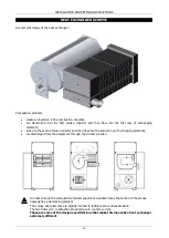
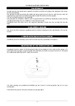
AIR OUTLET TEMPERATURE CONTROL PROBE
The electrical panel has a temperature probe placed at the ambient to be calibrated, or on the recirculation
air outlet duct. A shielded cable can be used to increase the length.
WARNING!
The temperature probe should be installed in an area having a non-turbulent air flow and not subjected to
radiation.
Содержание WIMBLEDON 145
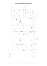
Страница 26: ...INSTALLATION AND SETTING INSTRUCTIONS 26 WIRING DIAGRAM Cod 10023495 TC Wiring diagram TYPE 1...
Страница 27: ...INSTALLATION AND SETTING INSTRUCTIONS 27...
Страница 28: ...INSTALLATION AND SETTING INSTRUCTIONS 28 Wiring diagram TYPE 2...
Страница 29: ...INSTALLATION AND SETTING INSTRUCTIONS 29...
Страница 39: ...TECHNICAL ASSISTANCE INSTRUCTIONS 39 NOTES...


