

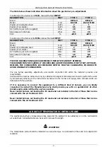


TECHNICAL ASSISTANCE INSTRUCTIONS
- 35 -
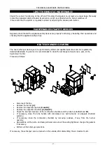
ELECTRICAL PANEL CONTROLS
The electrical panel has the following controls and signalling devices:
MAIN SWITCH
Installed on the equipment electrical main panel; it stops the main electric power supply to the equipment.
BUNER BLOCK INDICATOR
Red device, installed on the appliance electrical panel; it signal when the gas burner has stopped.
VOLTAGE INDICATOR
Green device, installed on the appliance electrical panel; it signals whether there is general electric voltage
or not.
SAFETY CHAIN SIGNAL
Red device, installed on the appliance electrical panel; it signal if the burner safety devices are operating.
The following buttons are also installed on the appliance:
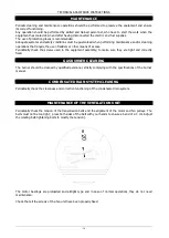
BURNER RESET BUTTON
Installed on the burner, it restarts the burner after a block.
LIMIT THERMOSTAT RESET BUTTON
Installed on the LIMIT safety thermostat, it restarts the burner after a block due to air overheating.
WARNING
he problem that activates the safety protection must be identified and removed before
restarting any device. In case of doubt, contact the nearest Authorised Assistance Centre,
which will provide you with the necessary technical help.
FAILURES AND TROUBLESHOOTING
ACTIVATION OF “LM” SAFETY THERMOSTAT
•
The LIMIT safety thermostat is activated when the outlet air is over-heated (see Technical Data for
calibration)
•
This leads to the immediate switch off of the burner.
•
After having removed the failure that caused the activation,
the system starts to operate by
pressing the release push-button, installed on the thermostat.
•
The signal lamp switches off and the equipment restarts working.
GAS BURNER SWITCH-OFF ACTIVATION:
•
The gas supply to the burner is interrupted if the latter does not switch on.
•
his leads to the immediate switch off of the burner. The ventilation unit does not stop before about
3 min.
•
After having removed the failure that caused the activation,
the system starts to operate by
pressing the release push-button, installed on the thermostat.
•
The signal lamp switches off and the equipment restarts working.
Содержание WIMBLEDON 145
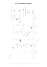
Страница 26: ...INSTALLATION AND SETTING INSTRUCTIONS 26 WIRING DIAGRAM Cod 10023495 TC Wiring diagram TYPE 1...
Страница 27: ...INSTALLATION AND SETTING INSTRUCTIONS 27...
Страница 28: ...INSTALLATION AND SETTING INSTRUCTIONS 28 Wiring diagram TYPE 2...
Страница 29: ...INSTALLATION AND SETTING INSTRUCTIONS 29...
Страница 39: ...TECHNICAL ASSISTANCE INSTRUCTIONS 39 NOTES...


