RECLINE EXCITE: Service & Maintenance Manual - rev. 2.4
Page 7.4
7.2. DISASSEMBLING THE CIRCUIT BOARDS ON THE
DISPLAY
7.2.1. 700
I AND
700
I
SP LED
VERSIONS
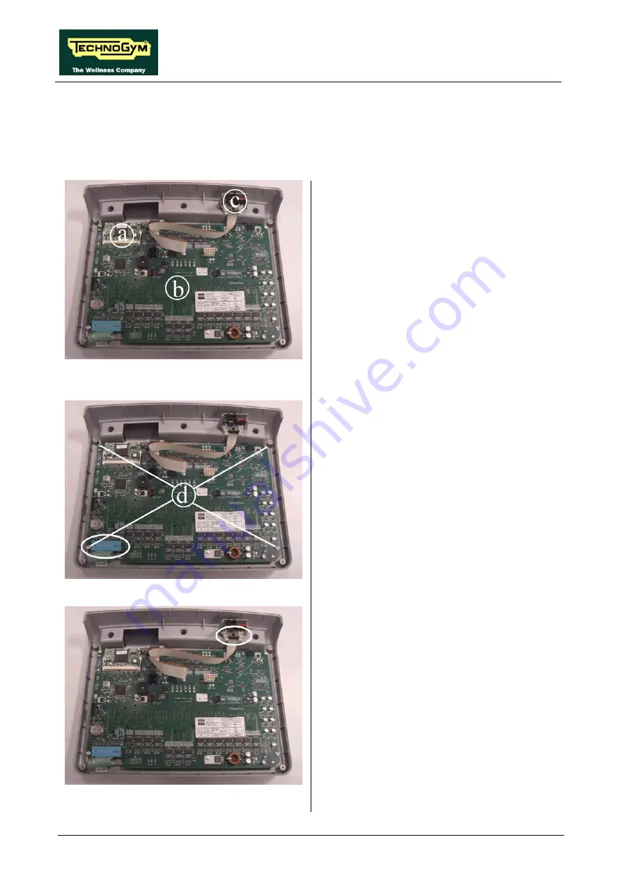
Figure 7.2-1
e
ay on a work bench. It is
w
ble its circuit boards:
y board
b
;
The CSafe board
c
.
Carry out the procedure described in paragraph
7.1. “Disassembling the display”.
Th n place the displ
no possible to disassem
•
The 386 board
a
;
•
The displa
•
Figure 7.2-2
386
:
t up
slightly.
Dis
board
a
1. Release the fixing tabs. The board will lif
2. Extract it from the connector on the display
board.
play board
b
:
1. Unplug the keyboard connector indicated in
the figure.
2. Back off the 4 screws
d
using a medium
Phillips screwdriver.
3. Remove the circuit board.
Figure 7.2-3
CSafe board
c
:
1. Unplug the connector indicated in the figure.
2. Remove the circuit board from the top.
To reassemble the electronics boards, carry out
the above steps in reverse order.
Содержание Recline 500
Страница 1: ...SERVICE MAINTENANCE MANUAL REV 2 4...
Страница 2: ......
Страница 4: ......
Страница 10: ...RECLINE EXCITE Service Maintenance Manual rev 2 4 Page vi Page intentionally left blank...
Страница 46: ...RECLINE EXCITE Service Maintenance Manual rev 2 4 Page 3 14 Page intentionally left blank...
Страница 58: ...RECLINE EXCITE Service Maintenance Manual rev 2 4 Page 4 12 Page intentionally left blank...
Страница 94: ...RECLINE EXCITE Service Maintenance Manual rev 2 4 Page 6 34 Page intentionally left blank...
Страница 134: ...RECLINE EXCITE Service Maintenance Manual rev 2 4 Page 7 40 Page intentionally left blank...
Страница 140: ...RECLINE EXCITE Service Maintenance Manual rev 2 4 Page 8 6 Page intentionally left blank...
Страница 172: ...RECLINE EXCITE Service Maintenance Manual rev 2 4 Page 9 32 Page intentionally left blank...
Страница 181: ......


