17
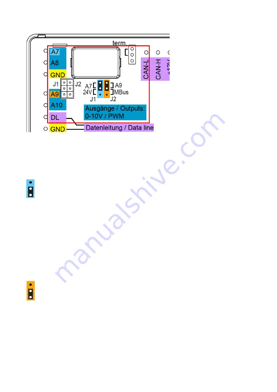
Terminal diagram for analogue outputs (0-10V / PWM)
Connections
A7
–
A10
are the positive pole; the
GND
connection is the negative pole.
If programmed as a "switching output", a maximum of 2
HIREL-230V
or
HIREL-PF
auxiliary relays
can be connected.
24V supply
Output
A7
can be converted to supply external devices with
24 V=
. To do this, plug-in jumper
J2
must
be moved from the upper to the lower position.
24V=
supply active
The combined total load of all devices with 12 V and 24 V supply must not exceed
6 W
.
Connection for 24 V supply to terminal
A7
and
sensor earth
(GND).
Outputs
A8
and
A10
are the analogue outputs (0-10 V/PWM).
A9
also remains an analogue output if
its M-Bus functionality is not used.
When using the 24 V supply, connections
A8
and
A10
become the
positive pole
; the GND connection
is the
negative pole
.
If programmed as a "switching output", a maximum of 1
HIREL-230V
or
HIREL-PF
auxiliary relay can
be connected.
M-Bus
Output 9
can be converted for reading in M-Bus meters. To do this, plug-in jumper
J1
must be moved
from the upper to the lower position.
M-Bus-interface active.
The connection is made at the terminals for
output 9
and
GND
.
The M-Bus has 2 wires:
M-Bus
(output 9) and
GND
(sensor earth). The power supply for reading data
from M-Bus devices is provided by the UVR610.
Cables can be routed with a star topology or in series (from one device to the next). Ring topology is
not permitted.
A two-wire screened cable is used as the M-Bus cable (e.g. telephone cable J-Y(ST)Y 2 x 2 x 0.8 mm).
The maximum total cable length depends on the number of M-Bus devices connected and the cable
cross-section.
Never run the M-Bus cable together with a CAN bus cable or DL bus cable in the same conduit.


