technetix AIMA3000.FT5X Скачать руководство пользователя страница 37

AIMA3000.FT5X Product User Manual

Technetix Group Limited

[email protected] 

 technetix.com

May/2016 - Version 1.0

37

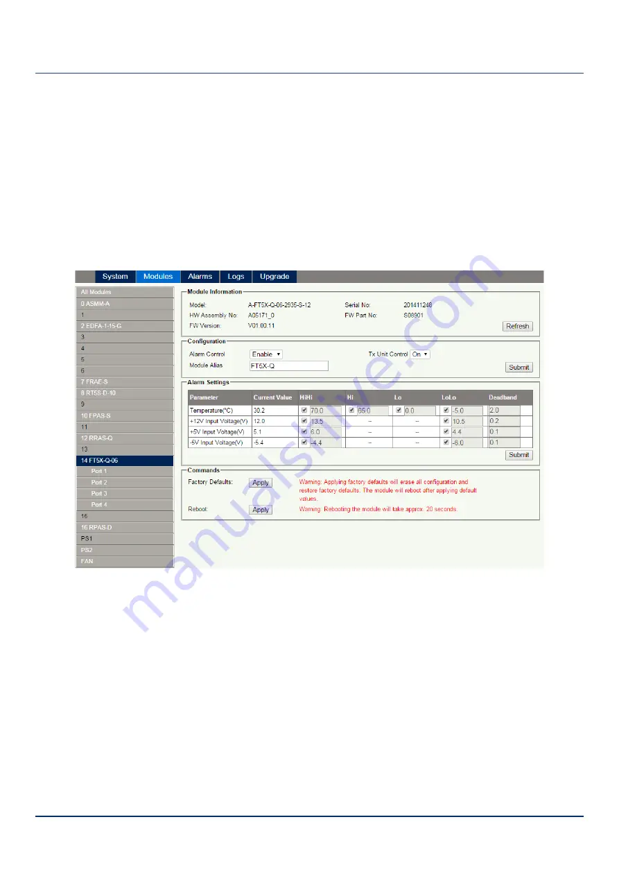
6.1.5 Alarm Monitoring Configuration
Monitoring Function ON / OFF

In Configuration section on Modules page, click Alarm Control to Enable/Disable Monitoring Function.

Temperature, +12V, +5V Voltage Alarm Levels Management

By default, temperature, +12 V, +5 V, - 5V voltage alarms are all set to ON. The check box ☑ as shown in 

Figure 6-7


controls the detection is set to ON or OFF. When the check box is checked (detection ON), the text in the text box will be 
solid black. The parameters cannot be changed. The parameters instruction is shown in 

Figure 6-7

Table 6-2

 below.

Figure 6-7

Содержание AIMA3000.FT5X

Страница 1: ...May 2016 Version 1 0 AIMA3000 FT5X 1550 nm Forward Transmitter Externally Modulated Product User Manual...

Страница 2: ...AIMA3000 FT5X Product User Manual Technetix Group Limited sales technetix com technetix com May 2016 Version 1 0 2 AIMA3000 FT5X 1550 nm Forward Transmitter Externally Modulated Product User Manual...

Страница 3: ...ock Diagram 12 3 5 Order Details 13 4 Module Characteristics 15 4 1 Module Appearance and Port Layout 15 4 1 1 Overview 15 4 1 2 Front Panel Layout 16 4 1 3 Rear Panel Layout 18 5 Installation 19 5 1...

Страница 4: ...ut Signal 33 6 1 2 Alarm Status Pages 34 6 1 3 Module operating voltage and temperature alarm 35 6 1 4 Module Port Alarms 36 6 1 5 Alarm Monitoring Configuration 37 6 1 6 Input Output Status Monitorin...

Страница 5: ...rocedure 6 Module Configuration Alarms Web management configuration instructions 7 Troubleshooting 8 Product Warranty 9 Declaration of Conformity Appendix A Default Alarm Limit Parameters Appendix B F...

Страница 6: ...d in this manual Asterisk Points marked with an asterisk means there is a corresponding note on the page 1 4 Technical Support If you need help in the process of setting up and maintaining an FT5X ple...

Страница 7: ...inside the device Do not power up before the cover and the panels of the equipment are installed and the enclosure is closed Cleaning Only use a damp cloth for cleaning the front panel Use a soft dry...

Страница 8: ...or 1550 nm transmissions for DWDM applications when used for optical ITU frequency grids Technetix AIMA3000 FT5X series transmitter is designed for multi service operators MSOs to increase network cap...

Страница 9: ...ing the quantity of transmitters at different fixed wavelengths All digital QAM loading from 45 MHz to 1200 MHz Link distance of up to 60 kilometers without any dispersion compensation required High d...

Страница 10: ...MHz RF flatness 0 75 dB RF input return loss 16 dB RF input level nominal 2 15 dBmV per channel AGC range 3 dB RF impedance 75 Laser Input RF level test point 20 dB 1 dB relative to laser input Isola...

Страница 11: ...management options Notes 1 Tunable version The factory default ITU optical channel is 33 and the ITU optical channel can be changed via the Web GUI 2 Standard option Contact a Technetix Sales Represe...

Страница 12: ...agram FT5X Table 3 1 RT5S Block Diagram Glossary Parameters Glossary 20 dB TP 20 dB Test Point RF IN RF Input RF MGC RF Input Gain PRE AMPLIFIER Pre Amplifier OMI AGC OMI Automatic Gain Control AMP Ou...

Страница 13: ...Quad 4 W Optical Output Power per Port 05 5 dBm 3 2 mw 06 6 dBm 4 mw fixed wavelength only X1X2 1 2 First Channel Last Channel 21 192 1 THz 1560 61 nm 23 192 3 THz 1558 98 nm 25 192 5 THz 1557 36 nm...

Страница 14: ...tter version Dual version X1 is first channel and X2 is the second channel Quad version X1 is first channel and X2 is the fourth channel The second and third channels are in between with default 200 G...

Страница 15: ...ser Manual Technetix Group Limited sales technetix com technetix com May 2016 Version 1 0 15 4 Module Characteristics 4 1 Module Appearance and Port Layout 4 1 1 Overview Front Panel Rear Panel Figure...

Страница 16: ...AIMA3000 FT5X Product User Manual Technetix Group Limited sales technetix com technetix com May 2016 Version 1 0 16 4 1 2 Front Panel Layout Figure 4 2 FT5X Front Panel Layout...

Страница 17: ...r 2 Status Indicator ON Green OFF Red Major Alarm Red 6 LSR2 TP Laser 2 Input Test Point 7 LSR3 LED Laser 3 Status Indicator ON Green OFF Red Major Alarm Red 8 LSR3 TP Laser 3 Input test point 9 LSR4...

Страница 18: ...re 4 3 Rear Panel Layout Table 4 2 FT5X Rear Panel Functions Serial Number Item Description 1 RF IN 1 RF Input 1 2 RF IN 2 RF Input 2 3 RF IN 3 RF Input 3 4 RF IN 4 RF Input 4 5 Air Vent Air vent allo...

Страница 19: ...esentative Necessary equipment and tools for installation Table 5 1 Necessary equipment and tools for installation Tools Modules Description Phillips screwdriver PH1 PH2 For use with the AIMA3000 chas...

Страница 20: ...ntil it reaches the multi pin connector DO NOT use excessive force when inserting the module but ensure the RF connectors at the rear of the module are securely connected with the chassis s RF connect...

Страница 21: ...he AIMA module fasten the spring loaded mounting screw Only use fingers to fasten the mounting screw DO NOT use a screwdriver 5 4 Connecting Optical Cables For the convenience of the user the AIMA3000...

Страница 22: ...roduct User Manual Technetix Group Limited sales technetix com technetix com May 2016 Version 1 0 22 2 Then pull the panel forward 3 Then lift up the handle and slide the fibre guide out of the front...

Страница 23: ...at the optical fibre tail does not become trapped or pulled tightly Fibre clip at rear for up to two connectors Handle at front 5 4 2 Using the Fibre Tray All optical fibres must be organised in a tid...

Страница 24: ...etix Group Limited sales technetix com technetix com May 2016 Version 1 0 24 2 Use the Fibre Guide Tool to organise the cables and wires in the fibre tray to prevent tangles and the blocking of the gu...

Страница 25: ...mpened with a static dissipative solvent to clean the angled surface Dry the surface using a dry lint free cloth To clean the front panel optical port use a special lint free swab that is designed for...

Страница 26: ...Module LEDs When the module has been installed if the chassis is powered all LED indicators on the front panel will show a blinking green light indicating the module is initiating If the input signal...

Страница 27: ...nical specifications Before testing the optical power meter must be calibrated Before measuring optical signals verify the interfaces are clean and undamaged CAUTION The device output optical power me...

Страница 28: ...and check the optical output power with a cleaned optical patch cord and a calibrated optical power meter Record the optical output level Connect a cleaned patch cord to the fibre output and to the r...

Страница 29: ...duct User Manual Technetix Group Limited sales technetix com technetix com May 2016 Version 1 0 29 6 Confirm that the Alarm Control is enabled Check the required selection and click on Submit to enabl...

Страница 30: ...etails on the web interface For login details and network setup please refer to the AIMA ASMM user manual If the same module is reinserted in the same slot the ASMM will restore the previous settings...

Страница 31: ...en will appear for the designated transmitter In the RF configuration screen Laser Output Control Input AGC Mode Modulation Mode OMI Offset RF MGC SBS Control and Alarm Settings become available For p...

Страница 32: ...t Power Configuration Input AGC Mode Enable AGC ON Automatic Gain Control OFF Manual Gain Control Laser Output Control Laser output control On Off OMI offset Change Factory Default OMI Value based on...

Страница 33: ...r 10 LOG number of channels On Figure 6 3 the interface displays the RF Input Power and the RF Composite Input Power The operator can calculate the power per channel When the different channels and le...

Страница 34: ...ay 2016 Version 1 0 34 6 1 2 Alarm Status Pages Click the Alarms tab on the menu bar to display an overview of the alarm status of all the installed modules as shown in Figure 6 4 below The each modul...

Страница 35: ...mation By clicking on FT5X under Modules tab the operator can view the module temperature and power supply voltage alarms The operator can utilise the status indicators to judge whether the module is...

Страница 36: ...ck on the Port 1 Port 2 Port 3 and Port 4 label under the module on the left column as shown in Figure 6 6 On the module port page the operator can view the Total Input Power Laser Temperature Laser O...

Страница 37: ...ol to Enable Disable Monitoring Function Temperature 12V 5V Voltage Alarm Levels Management By default temperature 12 V 5 V 5V voltage alarms are all set to ON The check box as shown in Figure 6 7 con...

Страница 38: ...0 38 Table 6 2 Modules Page Alarms Threshold Parameters Instruction Parameter Units HIHI HI Normal LO LOLO Dead Band Threshold changeable by user Default Alarm Enable Temperature C 70 65 0 5 2 N ON 12...

Страница 39: ...ion click on to toggle the alarms The customer can not change the monitoring parameters All transmitters have independent settings and they need to be adjusted separately See Figure 6 8 Figure 6 8 Tab...

Страница 40: ...de Control MODE OFF either port Blinking ON all ports Green always RF Critical ALM RF Input Power is too high HiHi or too low LoLo STAT LSR1 LSR2 LSR3 LSR4 Red RF Warning ALM RF Input Power is higher...

Страница 41: ...s Power OFF Power OFF Power OFF All All OFF Initiating AM Power ON During Module Power ON All Green 2 times sec No Alarm Normal operation Normal All Green Upgrading AM Firmware AM Upgrading Module upg...

Страница 42: ...d sales technetix com technetix com May 2016 Version 1 0 42 6 2 Logs Management The operator can view all the alarms of the modules in the chassis on the Logs Management page Click Logs to enter the L...

Страница 43: ...ocess At the same time you will be automatically redirected to the Network Management page The upgrade operation is then complete Figure 6 10 The upgrade file needs to be located on the PC that is con...

Страница 44: ...ng Detailed operations Click Modules tab and click the module to be configured as the page shown in Figure 6 11 Click Apply button in Factory Default section When finished the device configuration wil...

Страница 45: ...ulation Mode CW Modulated CW Retained Input AGC Mode ON OFF OFF Retained OMI offset dB 3 0 3 0 0 Retained RF MGC dB 3 0 3 0 0 Retained SBS Control Enable Disable Enable Retained Laser Output Status Al...

Страница 46: ...AIMA3000 FT5X Product User Manual Technetix Group Limited sales technetix com technetix com May 2016 Version 1 0 46 1 Click the module to be configured 2 Click Apply to reboot device...

Страница 47: ...aser Output Power is higher Hi or lower Lo Check the laser s Output Power If the Output Power is normal please contact Technetix technical support Laser is shutdown Laser Output Status Alarm is set En...

Страница 48: ...signal or adjust MGC to an appropriate value Laser Warning ALM or Laser shutdown Laser Output Status Alarm is set Enable Minor Check the laser s status STAT is red Operating environment Temperature is...

Страница 49: ...er s Name Technetix Manufacturer s Address Technetix Ltd Innovation House Technetix Business Park Albourne West Sussex BN6 9EB Product Name FT5X 1550 nm Externally Modulated Quad Transmitter Conforms...

Страница 50: ...6 Version 1 0 50 Appendix A Default Alarm Limit Settings Parameter Units HIHI HI Normal LO LOLO DeadBand Threshold changeable by user Default Alarm Enable Temperature C 70 65 0 5 2 N ON 12V Input volt...

Страница 51: ...rm Control Enable Disable Enable Retained Tx Unit Control ON OFF ON Retained Laser Output Control ON OFF ON Retained Modulation Mode CW Modulated CW Retained Input AGC Mode ON OFF OFF Retained OMI off...

Страница 52: ...technetix com May 2016 Version 1 0...

Отзывы: