2
3
Installation Instructions
By following these instructions carefully, your new hoist can be
assembled quickly to give safe, smooth and efficient operation
and an extended, trouble-free life.
Note: Use lifting equipment or extra people to lift & handle the
heavy parts.
1. The hoist must be installed under cover on a flat concrete
floor of minimum tensile strength Grade 25 MPa and minimum
thickness 100 mm with at least one layer of F72 reinforcing
mesh. The hoist must not be installed in a location where it is
exposed to the weather or explosive or flammable materials.
If the floor is not satisfactory, a new concrete base with a
minimum area of 3.7 x 1.6 m will need to be laid and allowed to
cure for one month before installing the hoist.
2. Install a mains isolator switch on a wall or column next to
where the hoist power column will be situated.
Note: This must be done by a qualified electrician.
For a three phase hoist, the power supply must be 415V, 50 Hz,
rated to carry 15A full load current and 33A inrush. The wiring
must be 3 core plus earth and a minimum 7-strand, 2.5 mm²
cross sectional area copper. For long runs larger wiring may be
required.
For a single phase hoist, the power supply must be 240 V, 50 Hz,
rated to carry 23A full load current and 132A inrush. The wiring
must be 2 core plus earth and a minimum 7-strand, 4 mm²
cross sectional area copper. For long runs larger wiring may be
required.
3. Unpack the hoist and place the base frame on the floor in the
desired position to allow easy access for vehicles and leaving a
clear 600 mm wide gap around the hoist for operator access.
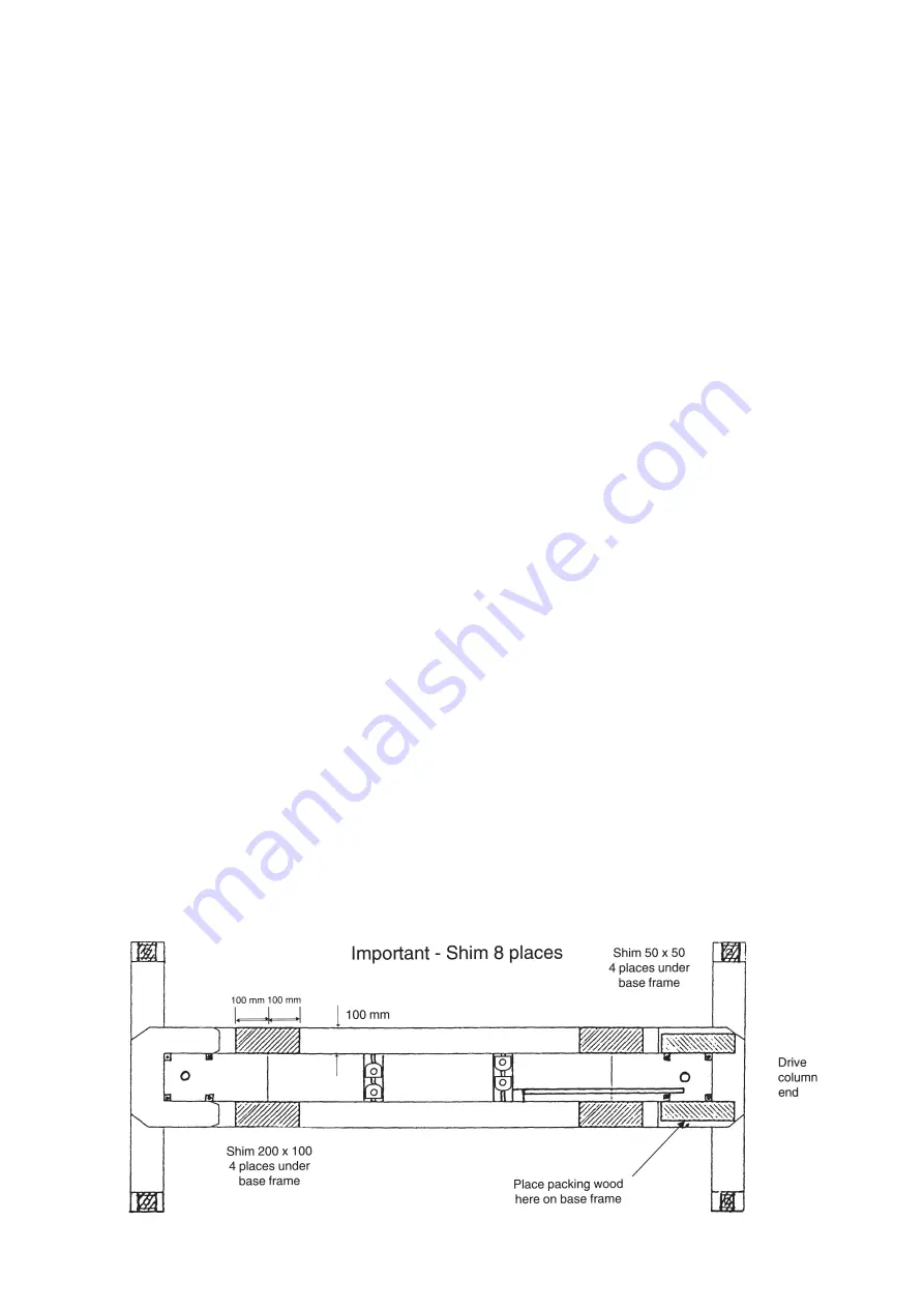
Note: The drive column goes on the end of the base frame that
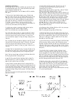
has the angle iron fitted inside (refer Fig.1)
Inspect the floor where the four hold-down bolts will go. The
hold-down bolts must not be installed within 200 mm of any
edge, crack or other fastener in the floor.
4. Level the base frame by adding 50 mm square metal shims,
with a 20 mm diameter hole in the centre, under the base frame
at the four hold-down bolt holes. When level, add 200 x 100 mm
metal shims under the base frame, as shown in Fig.1, to remove
any gap but without lifting the four corners of the base frame off
their shims.
Note: the maximum permissible gap between the base frame
and shims is 0.5 mm.
5. Drill and fit four hold-down bolts. The bolts must be 16
mm thread diameter and fitted in accordance with the
manufacturer’s instructions:
Approved expanding-type masonry anchors – Ramset Trubolt
T16125 and Hilti HSA stud anchor M16 x 140/25.
Note: The bottom edge of the expansion sleeve on the masonry
anchor must be a minimum of 75mm deep in the concrete when
tightened. If the base has been shimmed up a large amount,
longer anchors will be required to ensure this depth is reached.
Some authorities may not approve expanding type masonry
anchors. Approved adhesive masonry anchors: Ramset Chemset
capsule CHEM 16 and stud bolt M 16190 and Hilti adhesive
cartridge HEAM 16 x 125 and anchor rod HASM 16 x 190.
Note: These fasteners require a minimum concrete thickness
and hole depth of 125 mm.
6. Lay the drive chain in the base frame so that it runs between
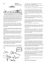
the chain rollers as shown in Fig.2.
Note: The joining link spring clip must be on top.
7. At the drive column at the end of the base frame lay two 38
mm thick x 400 mm long pieces of packaging wood along each
leg of the U-shaped plate as shown in Fig.1. Position the drive
column so it is laying on its back (as packed) with the column
base plate on top of the wood.
8. Secure the chain limit switch (which comes out of the bottom
of the column) out of the way, then stand the column up on
the pieces of wood. Position the column so the bolt holes in the
column and base frame roughly line up. Make sure the column
is stable on the wood and is being held at all times to prevent it
falling over.
9. Lay the chain limit switch and wiring in the base frame,
with the wiring lying inside the angle iron and the switch on
its mounting plate as in Fig.2. Reach under the column base
plate and fit the chain on to the sprocket (it may be easier if the
column is tilted back slightly). Keep holding the chain tight on
the sprocket. Tilt the column from side to side and remove the
pieces of packing wood (be careful it does not fall).
10. Bolt the column down using two M16 x 50 mm long and
two M10 x 35 mm long high tensile bolts. Leave the M16 bolts
undone about 4 mm (two turns). Fully tighten the M10 bolts
with a ring or socket spanner, then tighten the M16 bolts fully
with a torque wrench to 200NM (147 ft lbs).
Note: The bolts must be high tensile, identified by the marking
‘8.8’ on the head of the bolts.
Fig. 1


