background image

1-8

1. OUTLINE OF THE SYSTEM

EO10-33003A

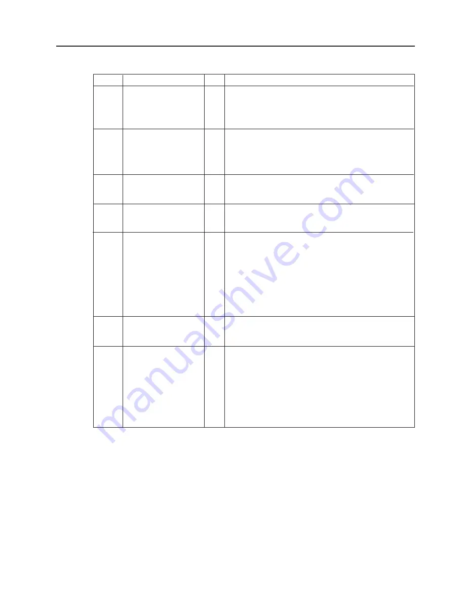
(9) Pin description

Pin No.

2

3

4

5

6

7

8

Signal

TD
(Transmit Data)

RD
(Received Data)

DSR
(Data Set Ready)

SG
(Data Set Ready)

DTR
(Data Terminal
Eeady)

CTS
(Clear to Send)

RTS
(Request to Send)

I/O

O

I

I

-

O

I

O

Description

Data line from which the printer sends data to the
host (send data line).
Logic "1" is "Low", and "0" "High".  It is LOW (MARK)
while no data is being sent.

Data line from which the printer receives data from
the host (receive data line).
Logic "1" is "Low", and "0" "High".  It is LOW (MARK)
while no data is being sent.

Input signal from the host.
It must be "High" for the printer to receive data.

Ground line for all data and control signals.

Output signal to the host.
When controlling the READY/ BUSY (DTR):
• Indicates that the printer is ready to receive data.
• When the receive buffer is nearly full, it is "Low",

and when the buffer is nearly empty, it becomes
"High".

When controlling the READ/BUSY (RTS):
After power is ON, it is always "High".

Input signal from the host.
It must be "High" for the printer to send data.

Output signal to the host.
When controlling the READY/BUSY (DTR):
• Indicates there is data to send to the host.
• After power is ON, it is always "High".
When controlling the READY/BUSY (RTS):
• When the receive buffer is nearly full, it is "Low",

and when the buffer is nearly empty, it becomes
"High".

1.5 ELECTRONICS SPECIFICATIONS

Содержание B-450 SERIES

Страница 1: ...ES Original Dec 1998 Revision Mar 2001 Document No EO0 33003A PRINTED IN JAPAN OWNER S MANUAL HS EO1 33019 PRODUCT DESCRIPTION EO10 33003A MAINTENANCE MANUAL EO18 33003A TABLE OF CONTENTS OWNER S MANU...

Страница 2: ...ecessary for safe handling are included in this manual All warnings and cautions contained in this manual and written inside or outside of the printer should be read and understood before handling or...

Страница 3: ......

Страница 4: ...PRINTED IN JAPAN EO0 33003A...

Страница 5: ...TEC Thermal Printer B 450 QQ SERIES Owner s Manual...

Страница 6: ...d used in accordance with the instruction manual may cause harmful interference to radio communications Operations of this equipment in a residential area is likely to cause harmful interference in wh...

Страница 7: ...e power cord plug from the outlet Do not use voltages other than the voltage AC specified on the rating plate as this may cause fire or electric shock Any other than the specified AC voltage is prohib...

Страница 8: ...ribbons DO NOT STORE the paper or ribbons where they might be exposed to direct sunlight high tem peratures high humidity dust or gas Ensure the printer is operated on a level surface Any data stored...

Страница 9: ...1 6 1 INSTALLING THE SUPPLY HOLDER UNIT 6 1 6 2 CONNECTING THE POWER CORD AND CABLES 6 1 7 LOADING THE RIBBON 7 1 8 LOADING THE PAPER 8 1 9 THRESHOLD SETTING 9 1 10 CARE HANDLING OF THE PAPER AND RIB...

Страница 10: ...erformance and life from your printer For most queries please refer to this manual and keep it safe for future reference 1 1 APPLICABLE MODEL B 452 TS10 QQ B 452 TS10 QQ US B 452 TS11 QQ PAC B 452 TS1...

Страница 11: ...mm sec 4 inch sec Maximum print width 105 7 mm 4 16 inches Dispensing modes Batch Continuous Strip Option and Cut modes Option Bothcutandstripmodesareavailableonlywhentheirrespectivemodules are fitte...

Страница 12: ...93 0 Type Spool type Width 60 mm 110 mm Length 300 m Outer diameter 65 mm max Use This cutter module uses a rotary cutter It cuts backing paper of labels and tag paper automatically in stop and cut mo...

Страница 13: ...nication error occurs when the paper ribbon ends or the printer is not operating cor rectly FEED Key Feeds paper PAUSE Key Pauses printing Resets the printer when paused or when an error occurs Fig 3...

Страница 14: ...s set to OFF the backing paper thickness setting can be changed by the following combination of DIPSWs 6 and 7 DIP SW Fig 4 1 WARNING Turn the POWER OFF before changing the DIP switches DIP SW No 1 2...

Страница 15: ...ower line conduits RS 232C Cable description The serial data cable used to connect the printer to the host computer should be one of the following two types NOTE Use an RS 232C cable with imperial inc...

Страница 16: ...Interface Cable RS 232C WARNING Turn the POWER SWITCH to OFF before connecting the power cord or cables Fit the two studs on the bottom of the printer into the holes in the supply holder unit 6 2 CON...

Страница 17: ...the power off and open the top cover 2 Move the head release lever toward the front of the printer and raise the print head block Fig 7 2 Fig 7 1 Print Head Block Head Release Lever Top Cover 3 Fit t...

Страница 18: ...ly side by fitting the protrusion into the notch 6 Turn the guide wheel in the arrow indicating direction to remove any slack of the ribbon NOTE Make sure that the ribbon has no wrinkles and the protr...

Страница 19: ...mm When using a paper roll of 38 mm 40 mm or 42 mm remove the spacers from the supply holders using the following procedure 1 Push both hooks of the spacer to remove it from the supply holder Keep the...

Страница 20: ...SupplyHolderGuide Lock Lever 4 Push both sides of the supply holder guides against the paper roll then lock them with the lock lever NOTE Make sure that the supply holders rotate slightly 5 Pass the...

Страница 21: ...7 Supply Holder Paper Guide Paper Platen A B A B Cutter type Whereacutterisfittedloadthepaperasstandardandfeeditthroughthecuttermodule NOTES 1 When using the cutter be sure to cut the backing paper b...

Страница 22: ...m the top edge of the label roll 2 First push the strip lever toward the printer to release the hook and then pull the strip lever 3 Pass the backing paper between the strip roller and the strip guide...

Страница 23: ...E key The paper will feed through the printer until the PAUSE key is released Release the PAUSE key after more than 1 5 labels have been fed Threshold setting is completed by this operation 6 Turn the...

Страница 24: ...l paper used for direct thermal printing must not have the specifications which exceed Na 800 ppm K 250 ppm and CL 500 ppm Some ink used on pre printed labels may contain ingredients which shorten the...

Страница 25: ...horized TOSHIBA TEC service representative Print Head Thermal Element WARNING 1 Be sure to disconnect the power cord prior to performing any maintenance 2 DO NOT POUR WATER directly onto the printer F...

Страница 26: ...Holder Roller Recessedportionofthebase Supply Holder Base Platen Black mark Feed gap sensor 11 2 COVERS The covers should be cleaned by wiping with a dry cloth or a cloth slightly dampened with a mil...

Страница 27: ...ust or foreign substances 7 Paper jams in the cutter unit can be caused by wear or residual glue from label stock on the cutter Do not use unspecified paper in the cutter If frequent jams occur in the...

Страница 28: ...trip Unit 1 First push the strip lever toward the printer to release the hook and then pull the strip lever 2 Remove the jammed paper if any 3 Clean the strip guide rollers A and B with a cloth moiste...

Страница 29: ...zed Service represen tative Problem 1 The paper is not fitted correctly 2 The paper path is jammed and does not feed smoothly 3 The installed paper type does not match the selected sensor 4 The instal...

Страница 30: ...er and ribbon are loaded correctly 2 Check that print head is set correctly 3 Check the cabling between the printer and the host Dirty print head Clean the print head Call your Authorized Service repr...

Страница 31: ...13 1 EO1 33006 APPENDIX APPENDIX APPENDIX ASCII Code Chart Font Sample Barcode Sample...

Страница 32: ...face board 2 2 Keyboard module 2 2 Strip mechanism 1 1 Strip module 2 2 P Paper 2 2 10 1 Paper jam 12 1 Power consumption 2 1 Power cord 1 1 6 1 Power switch 3 1 Print head 1 1 2 1 11 1 Print head cle...

Страница 33: ......

Страница 34: ...PRINTED IN JAPAN EO1 33006 E...

Страница 35: ...TEC Label Printer B 450 HS QQ SERIES Owner s Manual...

Страница 36: ...and used in accordance with the instruction manual may cause harmful interference to radio communications Operations of this equipment in a residential area is likely to cause harmful interference in...

Страница 37: ...indication Prohibited Do not plug in or unplug the power cord plug with wet hands as this may cause electric shock Do not place metal objects or water filled containers such as flower vases flower po...

Страница 38: ...ribbons DO NOT STORE the paper or ribbons where they might be exposed to direct sunlight high tem peratures high humidity dust or gas Ensure the printer is operated on a level surface Any data stored...

Страница 39: ...E SUPPLY HOLDER UNIT 6 1 6 2 INSTALLING THE SUPPLY COVER 6 1 6 3 CONNECTING THE POWER CORD AND CABLES 6 2 7 LOADING THE RIBBON 7 1 8 LOADING THE PAPER 8 1 9 THRESHOLD SETTING 9 1 10 CARE HANDLING OF T...

Страница 40: ...de a strip mechanism and cutter mechanism This manual contains general set up and maintenance information and should be read carefully to help gain maximum performance and life from your printer For m...

Страница 41: ...6 mm 4 08 inches Dispensing modes Batch Continuous Strip Option and Cut modes Option Bothcutandstripmodesareavailableonlywhentheirrespectivemodules are fitted Available bar code types JAN8 JAN13 EAN8...

Страница 42: ...up slow down area Outer roll diameter Thickness Backing paper label Thickness of backing paper Labeldispensingmode Item Batch mode Strip mode Cut mode 25 4 999 0 23 4 997 0 25 4 110 0 20 0 107 0 2 0...

Страница 43: ...a communication error occurs when the paper ribbon ends or the printer is not operating cor rectly FEED Key Feeds paper PAUSE Key Pauses printing Resets the printer when paused or when an error occur...

Страница 44: ...ting mode Sensor adjustment mode RAM clear mode Parameter Normal operation mode Program down load operation Remarks Transmission speed Baud rate Parity Stacker Auto media feed Selectable only when DIP...

Страница 45: ...ds Should not be tied to power line conduits RS 232C Cable description The serial data cable used to connect the printer to the host computer should be one of the following two types NOTE Use an RS 23...

Страница 46: ...it 6 2 INSTALLING THE SUPPLY COVER Fit both hooks of the supply cover onto the shafts of the supply holder and then gently close the supply cover Refer to Fig 6 2 NOTE After this section the supply co...

Страница 47: ...al Interface RS 232C WARNING Turn the POWER SWITCH to OFF before connecting the power cord or cables Parallel Interface Cable Centronics 6 3 CONNECTING THE POWER CORD AND CABLES 6 3 CONNECTING THE POW...

Страница 48: ...side 4 Pull the knob and set the ribbon core to the spring guide wheel Guide Wheel Protrusion Notch Knob Spring Guide Wheel Ribbon Core Take up side The printer is capable of printing in thermal trans...

Страница 49: ...side by fitting the protrusion into the notch 6 Turn the guide wheel in the direction indicated by the arrow to remove any slack on the ribbon NOTE Make sure that the ribbon has no wrinkles and the pr...

Страница 50: ...lder This supply holder accepts four sizes of label core 38 mm 40 mm 42 mm and 76 2 mm When using a paper roll of 38 mm 40 mm or 42 mm remove the spacers from the supply holders using the following pr...

Страница 51: ...ure that the supply holders rotate slightly Fig 8 4 Paper wound inside 6 Lift up the paper guide lock lever to release the paper guides 7 Draw the label towards the paper guides 8 Release the lock lev...

Страница 52: ...tting the feed gap sensor position and adjust the sensor position 11 Draw the label onto the platen Close the sensor cover and return the lock lever to lock the sensor cover tight 12 Close the print h...

Страница 53: ...n the label will cause the glue to stick to the cutter which may affect the cutter quality and shorten it s life Cutter Module Paper Outlet Paper Batch type Fig 8 9 Top Cover Fig 8 10 Strip type 1 Str...

Страница 54: ...y so that it does not touch the ribbon 3 Set sensor knob B to the same position number as the sensor knob A NOTE The sensor knobs A and B are set to the position 3 where the black mark is centred in t...

Страница 55: ...ver gently so that it does not touch the ribbon 3 Set the sensor knob B to the same position of the sensor knob A NOTE Sensor knobs A and B are set to position 3 where the black mark is centred on the...

Страница 56: ...E key The paper will feed through the printer until the PAUSE key is released Release the PAUSE key after more than 1 5 labels have been fed Threshold setting is completed by this operation 6 Turn the...

Страница 57: ...mal paper used for direct thermal printing must not have specifications that exceed Na 800 ppm K 250 ppm and CL 500 ppm Some ink used on pre printed labels may contain ingredients which shorten the pr...

Страница 58: ...horized TOSHIBA TEC service representative Print Head Thermal Element WARNING 1 Be sure to disconnect the power cord prior to performing any maintenance 2 DO NOT POUR WATER directly onto the printer F...

Страница 59: ...Holder Roller Recessedportionofthebase Supply Holder Base Platen Black mark Feed gap sensor 11 2 COVERS The covers should be cleaned by wiping with a dry cloth or a cloth slightly dampened with a mild...

Страница 60: ...e print head and platen then remove any further dust or foreign substances 8 Paper jams in the cutter unit can be caused by wear or residual glue from label stock on the cutter Do not use unspecified...

Страница 61: ...trip Unit 1 First push the strip lever toward the printer to release the hook and then pull the strip lever 2 Remove the jammed paper if any 3 Clean the strip guide rollers A and B with a cloth moiste...

Страница 62: ...zed Service represen tative Problem 1 The paper is not fitted correctly 2 The paper path is jammed and does not feed smoothly 3 The installed paper type does not match the selected sensor 4 The instal...

Страница 63: ...has been switched off and on all the print data in the printer is cleared Solution 1 Check that the paper and ribbon are loaded correctly 2 Check that print head is set correctly 3 Check the cabling...

Страница 64: ...13 1 EO1 33019 APPENDIX APPENDIX APPENDIX ASCII Code Chart Font Sample Barcode Sample...

Страница 65: ...board module 2 2 Strip mechanism 1 1 Strip module 2 2 P Paper 2 2 10 1 Paper jam 12 1 Power consumption 2 1 Power cord 1 1 6 2 Power switch 3 1 Print head 1 1 2 1 11 1 Print head cleaner 11 1 Print le...

Страница 66: ......

Страница 67: ......

Страница 68: ...PRINTED IN JAPAN EO1 33019 E...

Страница 69: ...TEC Thermal Printer B 450 SERIES Original Dec 1998 Revision Jan 2001 PRINTED IN JAPAN Product Description Document No EO10 33003A...

Страница 70: ...3 2 STRIP MODULE B 7904 H QM 3 2 3 3 KEYBOARD MODULE KB 80 QM 3 2 3 4 EXPANSION I O INTERFACE BOARD B 7704 IO QM 3 3 3 5 CENTRONICS INTERFACE BOARD B 7704 C QM 3 4 3 6 LAN I F BOARD B 7704 LAN QM 3 5...

Страница 71: ...t and the head history control system optimizes applied pulse signal to the head 5 The TS model can print data with the size of up to 114 0 mm W by 999 0 mm H at the maximum print speed of 101 6 mm se...

Страница 72: ...itch Top Cover Paper Guide Lock Lever Supply Holder AC Power Inlet Serial Interface Connector RS 232C Optional Keyboard Connector Parallel Interface Connector Centronics HS model Front View Rear View...

Страница 73: ...on mode and used to fine adjust values in the nagative direction Refer to the Maintenance Manual PAUSE Button Pauses printing Resets the printer when paused or when an error occurs Used to set the thr...

Страница 74: ...s attached Strip printing Strip mode is only available when an optional strip module is attached 6 Type of bar code two dimensional code 1 JAN8 EAN8 JAN13 EAN13 UPC A UPC B 2 EAN8 EAN13 UPC A UPC E 2...

Страница 75: ...e 15 Line Width 1 dot to 12 dots can be specified in units of 0 1 mm Guaranteed only when a line has more than 3 dots 16 Mechanism 1 Batch mechanism This is the standard mechanism which let the printe...

Страница 76: ...art bit Overrun error This error occurs when subsequent data is input before the data input to the UART from the host is read by the printer 6 Data entry code ASCII 8 bit code for European characters...

Страница 77: ...blank position in the receive buffer amount to 2KB or more When there are no blank position in the receive buffer the printer discards data received which exceeds the receive buffer capacity without...

Страница 78: ...It must be High for the printer to receive data Ground line for all data and control signals Output signal to the host When controlling the READY BUSY DTR Indicates that the printer is ready to recei...

Страница 79: ...graphic 4 Receiving buffer 5KB 5 Input Output circuit configuration and Input Output conditions 1 5 ELECTRONICS SPECIFICATIONS SN75189 or equivalent RD CTS DSR TD RTS DTR SN75188 or equivalent Fig 1...

Страница 80: ...e of the printer part on the bottom rear of the paper guide base and part on the sensor holder HS model This sensor comprised of the black mark sensor and feed gap sensor is located in two parts on th...

Страница 81: ...that the cutter cover is opened when the tab of the cutter cover is released from the actuator arm and the micro switch turns OFF 3 Slit sensor Transmissive sensor This sensor detects the rotation co...

Страница 82: ...9 Paper width when using 0 17 to 0 263 mm thick tag paper must be 25 4 to 37 mm 2 SUPPLY SPECIFICATIONS Infomation regarding the supply specifications contained in Product Description is essential to...

Страница 83: ...effective print width Outside the print range Outside the print range 4 15 mm 4 15 mm 105 7 mm 0 2 mm 114 0 mm Maximum paper width Fig 2 4 Fig 2 5 Fig 2 6 Design Non Print Area Fig 2 3 2 0 mm 10 0 mm...

Страница 84: ...6 mm or more and cut in the middle of the gap 8 Fanfold paper cannot be used 9 How to fix the label stock to the paper core Remove the labels from the backing paper for the minimum of 400 mm long and...

Страница 85: ...ng method 2 2 RIBBON No 1 2 3 4 5 7 8 6 Core Material Shape 2 2 RIBBON NOTE When purchasing ribbon locally they must meet the above size There may be TOSHIBA TEC approved ribbons which do not fall wit...

Страница 86: ...rratic paper advance and poor print quality Store the paper in plastic bags and always reseal after opening Unprotected paper can get dirty and the extra abrasion from the dust and dirt particles will...

Страница 87: ...enables the printer to be used in a LAN network by using the command language 3 OPTIONAL KIT 3 1 CUTTER MODULE B 7204 QM Fig 3 1 Print Head Cutter Platen Option Name Cutter module Strip module Program...

Страница 88: ...er to feed the backing paper No backing paper take up is provided 1 Print speed TS model Max 4 ips HS model Max 2 ips 2 Available minimum label length 25 4 mm 3 Available minimum label width 25 4 mm 3...

Страница 89: ...in No 1 2 3 4 5 6 7 8 9 10 11 12 Signal IN0 IN1 IN2 IN3 IN4 IN5 OUT0 OUT1 OUT2 OUT3 OUT4 OUT5 I O Input Input Input Input Input Input Output Output Output Output Output Output NOTE Controller side con...

Страница 90: ...ls OUT2 Pausing The printer is pausing OUT3 Error state The printer is in error state OUT4 Not used Always OFF OUT5 POWER ON The printer power is ON OUT6 Not used Always OFF External controller etc In...

Страница 91: ...LNET Server 240 seconds is set as the inactivity timer Data Session TCP Port for Centronics I F Output 1 session TCP Port for RS 232C I F Output 1 session LPR server 1 session LAN Hardware LAN Protoco...

Страница 92: ...I F Client Connection Server IP Address TCP Port no of server Connection retry count Connection Trigger Disconnection Timer value Receive Control Timer RS 232C I F Protocol ER Signal Password for the...

Страница 93: ...should be set to 9600 bps and NONE with the DIP switch respectively 10 Connector Pin and Signal Description 5 Printer Interface Centronics Interface It is a parallel output port for the data received...

Страница 94: ...t Loop Back Test Power ON Blink Red System Error Synchronizes with the ERROR LED ON Orange OFF Returns to the factory default setting OFF Operating Mode Wait status or while initializing ON Green Data...

Страница 95: ......

Страница 96: ...PRINTED IN JAPAN EO10 33003A...

Страница 97: ...TEC Thermal Printer B 450 SERIES Original Dec 1998 Revision Jan 2001 PRINTED IN JAPAN Maintenance Manual Document No EO18 33003A...

Страница 98: ...1 Pacing List 3 1 3 1 2 Installation Procedure 3 1 3 2 CENTRONICS INTERFACE BOARD B 7704 C QM 3 7 3 2 1 Packing List 3 7 3 2 2 Installation Procedure 3 7 3 3 EXPANSION I O INTERFACE BOARD B 7704 IO QM...

Страница 99: ...tor Voltage Fine Adjustment 6 29 6 3 13 Strip Wait Status Setting 6 30 6 3 14 Threshold Manual Fine Adjustment for the Black Mark Sensor 6 31 6 3 15 Threshold Manual Fine Adjustment for the Feed Gap S...

Страница 100: ...ING CONNECTION 8 1 8 4 DOWN LOAD PROCEDURE 8 2 8 4 1 Program download mode 8 2 8 4 2 Program file maintenance mode Deleting program files 8 3 8 5 DOWNLOAD PROCEDURE WINDOWS Version 8 4 CAUTION 1 This...

Страница 101: ...ter from the carton 3 Unpack the accessories from the carton 1 1 PROCEDURE Side Pad R Printer Owner s Manual Cushion Cushion Carton Power Cord Side Pad L Supply Holder Base Supply Holder Dust Cover Ba...

Страница 102: ...rinter 7 Place the printer on a level surface 1 2 CHECKS 1 Check for damage or scratches on the printer 2 Confirm that none of the accessories are missing NOTE Keep the carton pads and cushions for la...

Страница 103: ...h lubrication is needed Although the frequency of lubrication varies according to how much the machine is used at least it is necessary to lubricate before the machine becomes dry It is also necessary...

Страница 104: ...6 Replace the CPU PC board with a new one and then reassemble in the reverse order of removal Fig 2 3 CPU PC Board SMW 3x6 Screw PT 3x10 Screw SMW 3x6 Screw PT 3x10 Screw Ground Wire CPU PC Board PT...

Страница 105: ...moving the motors refer to Section 2 1 to detach the top cover and CPU PC board 2 2 1 Ribbon Motor 1 Remove the two PT 3x10 screws and harnesses to detach the ribbon motor attaching plate Fig 2 4 PT 3...

Страница 106: ...SMW 2 6x6 screws to detach the two ribbon motors from the ribbon motor attaching plate 3 Replace the ribbon motors with new ones and then reassemble in the reverse order of removal SMW 2 6x6 Screw Rib...

Страница 107: ...otor 3 Replace the stepping motor with a new one and then reassemble in the reverse order of removal Fig 2 7 PT 3x10 Screw Stepping Motor Ass y SMW 3x6 Screw Stepping Motor 1 Remove the two PT 3x10 sc...

Страница 108: ...fan motor harness from CN9 and CN8 on the CPU PC board Side Cover R PT 3x10 Screw CPU PC Board Power Harness CN8 1 Refer to Section 2 1 to detach the top cover 2 Remove the T 3x10 screw to detach the...

Страница 109: ...REPLACEMENT 2 3 REPLACING THE PS UNIT Fig 2 10 4 Release the two hooks securing the printer unit 5 Detach the printer unit from the bottom cover Fig 2 11 CPU PC Board Hook Head Release Lever R Printe...

Страница 110: ...g 2 12 6 Detach the PS unit from the bottom cover 7 Disconnect the power harness from CN3 on the PS unit Remove the SMW 4x8 screw to release the ground wire of the inlet ass y Fig 2 13 Bottom Cover PS...

Страница 111: ...OR UNIT REPLACEMENT 2 3 REPLACING THE PS UNIT Fig 2 14 8 Disconnect the inlet ass y from CN1 on the PS unit 9 Replace the PS unit with a new one and then reassemble in the reverse order of removal PS...

Страница 112: ...int Head Block Head Release Lever R 1 Push down the head release lever R to open the print head block CAUTION 1 NEVER touch the element when handling the print head 2 NEVER touch the connector pins To...

Страница 113: ...ively NOTE When re connecting the flat cable be careful of the terminal orientation 4 Detach the head control PC board from the three locking supports that secure it to the CPU PC board 2 5 REPLACING...

Страница 114: ...CB TR 1 Push down the head release lever R to open the print head block Refer tp Sectopm 2 4 2 Remove the sensor holder from the sensor holder arm 2 6 REPLACING THE MEDIA SENSOR Fig 2 19 3 Remove the...

Страница 115: ...harness from the sensor PCB TR and remove the sensor PCB TR from the sensor holder by releasing it from the two rivets Fig 2 21 6 Replace the sensor PCB TR with a new one and then reassemble in the re...

Страница 116: ...ttom cover Refer to Section 2 3 5 Disconnect the harness from the sensor PCB LED which is attached to the bottom of the printer unit Then remove the rivet to detach the sensor PCB from the printer uni...

Страница 117: ...sor PCB TR to the left side to release it from the sensor holder and disconnect the harness from the sensor PCB TR 5 Replace the sensor PCB TR with a new one and then reassemble in the reverse order o...

Страница 118: ...nd lift the sensor block 2 6 REPLACING THE MEDIA SENSOR Fig 2 26 NOTE In the above picture the head release lever R is removed to indicate the position of the sensor release lever clearly In the actua...

Страница 119: ...ensor PCB LED from the sensor block 7 Replace the sensor PCB LED with a new one and then reassemble in the reverse order of removal NOTE Secure the sensor PCB LED with the rivet together with the slid...

Страница 120: ...DPI EXPIO PC board respectively 2 7 REPLACING THE 600 DPI EXPIO PC BOARD FOR B 452 HS MODEL 4 Remove the two B 3x6 screws and detach the 600 DPI EXPIO PC board from the locking support that secures i...

Страница 121: ...ER MODULE B 7204 QM 3 1 CUTTER MODULE B 7204 QM Fig 3 2 Cutter Unit 1 pc Cutter Harness 1 pc Cutter Cover 1 pc Installation Manual 1 pc Double Sems Screw SMW 3x8 1 pc Cutter Ground Plate B 1 pc Ferrit...

Страница 122: ...ach the side cover L 3 1 CUTTER MODULE B 7204 QM Fig 3 3 Fig 3 4 4 Move the head release lever toward the front of the printer to open the print head block 5 Unhook and remove the platen block from th...

Страница 123: ...leinasafeplacesothatitmaybereplacedshouldthecutter module be removed in the future 7 Replace the platen block Fig 3 7 8 Remove the PT 3x10 screw which secures the stepping motor ass y Secure the cutte...

Страница 124: ...tter harness through the square hole indicated in the following picture so that the 13 pin connector comes to the CPU PC board side 11 Wind the cutter harness around the ferrite core one time and conn...

Страница 125: ...cutter unit 13 Insert both sides of protruding portions of the cutter unit into the slits in front of the printer Fig 3 13 14 Secure the cutter unit to the printer with the enclosed SMW 3x8 screw Fig...

Страница 126: ...cover into the notches of the cutter unit to attach the cutter cover 3 1 CUTTER MODULE B 7204 QM Fig 3 15 16 Reassemble the top cover side cover R and side cover L in the reverse order of removal NOT...

Страница 127: ...Manual 1 pc Locking Support WLS 16 0 1 pc 3 2 CENTRONICS INTERFACE BOARD B 7704 C QM CENTRO Flat Cable 1 pc 3 2 2 Installation Procedure 1 Turn the power off 2 Open the top cover and remove the two PT...

Страница 128: ...11 on the CPU PC board with the CENTRO flat cable Fig 3 18 3 2 CENTRONICS INTERFACE BOARD B 7704 C QM Fig 3 19 CPU PC Board CN11 CENTRO Flat Cable Centronics I F Board CN1 Locking Support CPU PC Board...

Страница 129: ...tallation Manual 1 pc Locking Support WLS 16 0 1 pc Expansion I O Cable 1 pc 3 3 2 Installation Procedure 1 Turn the power off 2 Open the top cover and remove the two PT 3x10 screws Refer to section 3...

Страница 130: ...oard to CN7 on the CPU PC board with the expansion I O cable 7 Reassemble the top cover and side cover L in the reverse order of removal NOTES 1 Be careful not to pinch the harnesses by the covers whe...

Страница 131: ...1 pc Installation Manual 1 pc 3 4 2 Installation Procedure 1 Turn the power off 2 Open the top cover and remove the two PT 3x10 screws Refer to section 3 1 3 Disconnect the KEY LED harness from CN14 o...

Страница 132: ...ow 3 5 LAN I F BOARD B 7704 LAN QM LAN Board 1 pc Fig 3 26 3 5 2 Installation Procedure 1 Turn the power off 2 Open the top cover and remove the two PT 3x10 screws Refer to section 3 1 3 Disconnect th...

Страница 133: ...port and two bind screws B 3 x 6 Connect the other end of the LAN flat cable to J3 on the LAN board Fig 3 28 CN11 LAN Flat Cable CPU PC Board NOTE Do not change the setting of the DIP switch installed...

Страница 134: ...rinter power OFF before connecting the KB 80 QM to the printer 3 6 1 Installation Procedure 1 Turn off the printer power 2 Connect the DIN cable of the KB 80 QM to the DIN connector of the B 450 print...

Страница 135: ...be short circuited causing electric shock fire or machine failure 3 7 1 Packing List All the following parts are supplied with the kit Make sure you have all items shown below Installation Manual 1 pc...

Страница 136: ...board to detach the side cover L Refer to section 3 1 4 Remove the PT 3x10 screw to detach the side cover R Refer to section 2 3 5 Attach the enclosed cable clamps MSC 1 and DKN 5 as shown below Revi...

Страница 137: ...3 34 Ground Wire Platen Block Square Hole Frame Strip Sensor Ass y Harness Purple Harness Black 7 Insert the two harnesses black and purple of the enclosed strip sensor ass y and the ground wire into...

Страница 138: ...e tabs and then lead it to the front of the printer Fig 3 36 Platen Strip Sensor Harness Purple Tab 9 Connect the strip sensor harness purple to the strip sensor LED and then fit the strip sensor LED...

Страница 139: ...o the printer 2 After reassembling the sensor block in the HS model check for a smooth adjustment of the media sensor position If the strip sensor harness is entangled in the media sensor harness a sm...

Страница 140: ...rip base 13 Connect the strip sensor harness black to the connector of the strip module and secure the ground wire to the strip module with the screw as shown in the figure below 14 Unhook and remove...

Страница 141: ...ate Fig 3 43 Fig 3 44 Platen Block Paper Scale Strip Plate Strip Module Left Side B A Guide Plate Strip Module Right Side Guide Plate Strip Module A White Screw B Slit Exchange 16 Attach the strip mod...

Страница 142: ...ground wire to attach the strip plate L to the frame base with the enclosed PT 3x8 screw Ensure that the strip plate L holds the plate behind the hook plate L Strip Module PT 3x8 Screw Strip Plate L...

Страница 143: ...only Release the head control PC board from the three locking supports that secure it to the CPU PC board 23 Wind the strip sensor around the enclosed ferrite core one time and connect the strip senso...

Страница 144: ...platen block detached in STEP14 to the printer and close the print head block Fig 3 51 Print Head Block Platen Block Strip Module 25 Reassemble the side covers L and R and the top cover in the revers...

Страница 145: ...Problems Cause Solution 1 Input voltage to the printer is not within the rated voltage 2 Output voltage from the printer is not within the rated voltage 3 CPU PC Board is not applied with voltage 4 Fa...

Страница 146: ...START keyisreleasedwithin3secondsinthepausestate theprinterwillresume printing without displaying the reset menu 2 If the RESTART key is released within 3 seconds in the error and pause state the prin...

Страница 147: ...eed or issue is attempted with the head block opened The print head is too hot Ribbon error Ribbon error ribbon break An error has occurred when writing data into the flash memory A deletion error occ...

Страница 148: ...in the pause state This LED state indicates the printer is in reset mode 4 Press the PAUSE key The printer returns to the initial state NOTES 1 When the printer is restorable it will enter the reset m...

Страница 149: ...nt position misaligned the printer cannot print data on a proper position therefore feed one or two pieces of paper to set the paper to the proper position before printing Also sets the feed speed adj...

Страница 150: ...emory Undefined command is retrieved A zero dividing error occurred A momentary power failure occurred Backup EEPROM is not read written properly The stacked paper is full The label issue is attempted...

Страница 151: ...cation mode and the language of LCD message and feed speed adjustment are available in this mode Test Print Mode See page 6 38 Print condition and test print type slant lines characters and bar codes...

Страница 152: ...e error can be cleared by pressing the PAUSE key and the printer restores to the copy print tone selection Auto reissue is not performed after the error is cleared 2 The default parameter at power on...

Страница 153: ...n error the printer will display the error message and stop printing The error status can be cleared by the PAUSE key however the display will return to the initial display 1 DIAGNOSTIC Software Versi...

Страница 154: ...0 to 200 0 km 0 to 1000000 times 0 to 2000 hours 0 to 255 hours 0 to 15 times 0 to 15 times 1 2 3 4 5 6 7 8 9 10 11 12 13 14 15 16 17 18 33 35 TL FEED 0 0km FEED 0 0km PRINT 0 0km CUT 64 RIBBON 0h 23...

Страница 155: ...rmal Direct Parity Strip Status Euro Code TT BLOCK Contents 10 0 to 10 0 99 5 mm to 99 5 mm 15 step to 0 step PC 850 PC 851 PC 1252 LATIN9 PC 8 PC 855 PC 1253 ARABIC PC 852 PC 1250 PC 1254 PC 857 PC 1...

Страница 156: ...st two digits of the checksum are usually 0 2 FONT ROM Check PROGRAM V1 3 A FMRM0050901 EC00 Checksum Part No of ROM or software Revision No Space or A to Z Software version No ROM name PROGRAM Progra...

Страница 157: ...2000 6 2 SELF TEST MODE 5 EEPROM Check 6 DRAM Check EEPROM OK Read write check OK Datainthecheckareacanbeproperlyread written NG Data in the check area cannot be properly read written EEPROM Backup m...

Страница 158: ...ind 0 The detecting point is positioned outside the slit 1 The detecting point is positioned inside the slit Slit Sensor Feed 0 The detecting point is positioned outside the slit 1 The detecting point...

Страница 159: ...4 5 6 7 8 9 10 11 12 13 14 15 B 452 TS model 1731 to 1759 1703 to 1730 1674 to 1702 1645 to 1673 1617 to 1644 1588 to 1616 1559 to 1587 1531 to 1558 1502 to 1530 1473 to 1501 1444 to 1472 1416 to 144...

Страница 160: ...No 8 7 6 5 4 3 2 1 0 0 0 0 0 0 0 0 DIP SW1 0 OPEN 1 ON DIN OK OK Loop back check succeeded NG Loop back check failed 12 Loop back check with the Expansion I O EXP I O OK OK Loop back check succeeded N...

Страница 161: ...J B 0 B F O T C O D E P C 8 5 0 N Z E O F O N T 0 R Power off T O E A D J T 0 N S T T U S T Y P E 1 A T H E S H O L D R 1 0 V R T H E S H O L D T 0 7 V R K A J I C O D E T Y P E 1 N T O E A D J D 0 N...

Страница 162: ...is parameter the print tone is fine adjusted at the thermal direct printing The longer the print pulse width the darker the print tone becomes The shorter the lighter the print tone becomes The charac...

Страница 163: ...Key fine adjustment value 10 0 mm PC fine adjustment value B 450 TS 10 0 mm B452 HS 50 0 mm When the value reaches the maximum the value remains unchanged even if the subsequent fine adjustment is pe...

Страница 164: ...ion fine adjustment value using the expression provided on page 6 17 6 3 PARAMETER SETTING MODE 6 3 2 Cut Strip Position Fine Adjustment 1 D I A G 2 P A R A M E T E R S E T C U A D J 0 0 m m T Power o...

Страница 165: ...the key key Pressing the key one time is a 0 5 mm change up to 9 5 mm See NOTE 2 key Pressing the key one time is a 0 5 mm change up to 9 5 mm See NOTE 2 6 3 PARAMETER SETTING MODE 6 3 3 Back Feed Len...

Страница 166: ...e Adjustment Example Cut Position Fine Adjustment Example A A A A A A A A A A A A 0 0 mm Feed Direction 10 0 mm 10 0 mm 10 mm 10 mm Fig 6 3 Fig 6 4 Fig 6 5 0 0 mm Feed Direction 10 0 mm 10 0 mm Black...

Страница 167: ...However use of this method will leave one or two printed label s between the print head and the cutter Feed or print the label s to remove them a Formula for cut position fine adjustment value Cut po...

Страница 168: ...by subtracting 2 mm from the label pitch that is set the gap length to 2 mm If the print format hangs over the gap as a result correct the print start position If the print stop position is improper...

Страница 169: ...3A 6 DIAG TEST OPERATION 6 3 PARAMETER SETTING MODE Back Feed Length Fine Adjustment Example A A A A A A A A A A A A 0 0 mm Feed Direction 3 0 mm 3 0 mm 3 0 mm 3 0 mm Print start position Fig 6 14 Fig...

Страница 170: ...change up to 99 5 mm See NOTE 2 key Pressing the key one time is a 0 5 mm change up to 99 5 mm See NOTE 2 6 3 PARAMETER SETTING MODE 6 3 4 X Axis Fine Adjustment Power off 1 D I A G 2 P A R A M E T E...

Страница 171: ...he value reaches the coordinate 0 the value remains unchanged even if the subsequent fine adjustment is performed in the negative direction 3 X axis fine adjustment cannot be used in self test mode or...

Страница 172: ...ing the key one time is a 1 step change up to 10 steps See NOTE 2 key Pressing the key one time is a 1 step change up to 10 steps See NOTE 2 6 3 PARAMETER SETTING MODE 6 3 5 Print Tone Fine Adjustment...

Страница 173: ...key key Pressing the key one time is a 1 step change up to 10 steps See NOTE 2 key Pressing the key one time is a 1 step change up to 10 steps See NOTE 2 6 3 6 Print Tone Fine Adjustment Thermal Direc...

Страница 174: ...memory by pressing the key 6 3 PARAMETER SETTING MODE 6 3 7 Font Code Selection Power off Turn on the power while holding down the SHIFT key Press the key Press the key seven times Select either chara...

Страница 175: ...R SETTING MODE 6 3 8 Font Zero Selection Power off Turn on the power while holding down the SHIFT key Press the key Press the key eight times Select either zero font with the key or key See NOTE 1 Pre...

Страница 176: ...ion with the key or key See NOTE 1 Press the ENTER key Press the key Continued on Section 6 3 10 Control Code Selection 1 D I A G 2 P A R A M E T E R S E T X O R E A D Y A U T O N S E T O P R I N T T...

Страница 177: ...off Turn on the power while holding down the SHIFT key Press the key Press the key ten times Select control code with the key or key See NOTE 1 Press the ENTER key Press the key Continued on Section...

Страница 178: ...ep change up to 0 step See NOTE 2 6 3 11 Ribbon Take up Motor Voltage Fine Adjustment 1 D I A G 2 P A R A M E T E R S E T Power off R I B O N A D J F 0 B S E T O P R I N T T E R Y E E N T N C S O Pres...

Страница 179: ...is a 1 step change up to 0 step See NOTE 2 6 3 PARAMETER SETTING MODE 6 3 12 Ribbon Feed Motor Voltage Fine Adjustment 1 D I A G 2 P A R A M E T E R S E T Power off R I B O N A D J B 0 B S E T O P R...

Страница 180: ...est command is sent during printing the printer will always send 05H regardless of the setting 2 A changed strip wait status is stored in keyboard memory by pressing the key key Status type 2 A strip...

Страница 181: ...3 15 Threshold Manual Fine Adjustment for the Feed Gap Sensor S E T O P R I N T T E R Y E E N T N C S O Press the ENTER key or C key Press the C key 6 3 14 Threshold Manual Fine Adjustment for the Bla...

Страница 182: ...a 0 1V change up to 0 0V key Pressingthe keyonetimeisa 0 1V change up to 4 0V Power off Turn on the power while holding down the SHIFT key Press the key Press the key fifteen times 1 D I A G 2 P A R...

Страница 183: ...YPE 1 Windows code TYPE 2 Original code Press the key or key to select the Kanji code Press the ENTER key Press the key Continued on Section 6 3 17 Feed Speed Adjustment S E T O P R I N T T E R Y E E...

Страница 184: ...econds enables a fast forward 2 A changed feed speed is stored in keyboard memory by pressing the key 6 3 PARAMETER SETTING MODE key Pressing the key one time is a 0 1 change up to 10 0 key Pressing t...

Страница 185: ...123 ABC ABC ABC The top edge of one label tag Pre print Pre print 0 0 Print out became shrunk Print is out of po sition due to a shrunk printing Adjust the feed speed to print in the correct posi tio...

Страница 186: ...key 6 3 18 Character Code 5CH Selection Power off Turn on the power while holding down the SHIFT key Press the key Press the key eighteen times Select either character code 5CH with the key or key See...

Страница 187: ...the key one time is a 1 H change up to 20 H key Pressing the key one time is a 1 H change up to FFH Power off Turn on the power while holding down the SHIFT key Press the key Press the key eighteen t...

Страница 188: ...ch without cut LABEL LENGTH 76 mm LABEL WIDTH 104 mm PAPER FEED Feed Operating procedure for the test mode is provided below Power off Turn on the power while holding down the SHIFT key Press the key...

Страница 189: ...the C key To C of the preceding page Press the C key To C of the preceding page To be continued on D of the next page Set the sensor type 5000 Print count 5000 1000 Print count 1000 500 Print count 5...

Страница 190: ...500 Label length 500 mm FEED NO FEED 499 Label length 499 mm 498 Label length 498 mm 39 Label length 36 mm 38 Label length 38 mm 37 Label length 37 mm C WITH CUT Issue and cutting H PEEL OFF On deman...

Страница 191: ...ause of an error 6 Pressing the key changes the label length 1 mm pressing the key changes 1 mm 7 When an error occurs during a test print the error message is displayed and printing is stopped The er...

Страница 192: ...NT is selected 5 pcs of the 3 dot slant line labels bar code labels and character labels are printed respectively after one label is fed Test Print Sample Slant line 1 dot Slant line 3 dot Characters...

Страница 193: ...has been performed in online mode an auto reverse feed is not performed when starting a test print 2 Even if the auto paper feed has been performed in test print mode an auto reverse feed is not perfo...

Страница 194: ...in this mode is printed as data of sensor 2 in Automatic diagnosis printing in self test mode 6 5 1 Thermistor Check Thermistor check should be performed to check the environmental temperature and pr...

Страница 195: ...ey down until an asterisk is displayed More than 3 seconds Indicates adjustment complete P L V R 4 3 V E See NOTE 2 Press the C key Press the C key Press the key twice NOTES 1 Be sure to adjust the bl...

Страница 196: ...gap sensor can detect the backing paper no label See NOTE 1 Holding the RESTART key down until an asterisk is displayed More than 3 seconds Ex The former value is displayed See NOTE 2 Indicates the a...

Страница 197: ...et the tag paper so that the sensor can detect the white part of the paper 6 Press and hold the PAUSE key for 3 seconds or more 7 The power LED blinks when the black mark sensor adjustment is complete...

Страница 198: ...the PAUSE key The paper will feed through the printer until the PAUSE key is released Release the PAUSE key after more than 1 5 labels have been fed Threshold setting is completed by this operation In...

Страница 199: ...ear functions Maintenance counter clear and parameter clear in the parameter setting mode After referring to the following table specify and clear or initialize the data RAM Clear Mode Table 6 8 RAM C...

Страница 200: ...CLEAR Item X axis fine adjustment Character code selection Font zero selection Code 5CH selection Transmission control mode Control code selection Strip wait status setting Status response Threshold...

Страница 201: ...urn on the power while holding down the SHIFT key Press the key four times Press the key twice Press the key Press the ENTER key Turn off the power See NOTE Press the ENTER key Press the C key 1 D I A...

Страница 202: ...DE When using the KB 80 QM optional keyboard Power off Turn on the power while holding down the SHIFT key Press the key four times Press the key twice Press the key Press the ENTER key Turn off the po...

Страница 203: ...M clear is completed when all 3 LED s blinks 7 Turn the power OFF 8 Set the DIP Switches to original position 6 9 2 Parameter Clear 1 Turn the power OFF 2 Set the DIP switches to enter the parameter c...

Страница 204: ...Press the key five times Press the key 1 D I A G 6 L A M I F S E T Press the key M Y I P A D D R E S S 1 9 2 3 8 2 5 4 2 5 3 0 Press the key G A E W A Y A D D R E S S T 0 0 0 0 0 0 0 0 0 0 0 0 Press...

Страница 205: ...or communication by Centronics I F Client Connection Server IP Address TCP port No of server RS 232C I F Protocol Connection Retry count Connection Trigger Disconnection Timer value Initial Socket Mod...

Страница 206: ...ection 6 4 TEST PRINT MODE 3 The B 452 TS model does not support this function If this function is tried the LCD will display NOT SUPPORTED 6 11 HEAD BROKEN ELEMENT CHECK B 452 HS MODEL The printer au...

Страница 207: ...is provided for the printer 7 2 SETUP The transmission control code must be set to either automatic selection or manual selection I You cannot perform a down load with any other control codes Refer t...

Страница 208: ...o the hard disk and start the program in the hard disk 8 After starting the exe file BMMS the following menu is displayed indicates the main pro gram version A 9 Select the program 10 Start the progra...

Страница 209: ...rates properly and the main program version and checksum is printed on the label 7 4 ERROR CODE Error Code 06 07 50 51 57 88 90 92 93 94 95 97 98 99 Error Communication error Error is detected during...

Страница 210: ...Windows 98 insert Setup Disk 1 2 into the PC floppy drive 3 Click on the START button then highlight RUN and click on RUN 4 When the RUN display appears as in below type in A setup and click on OK 5...

Страница 211: ...d parity to 9600 bps and EVEN respectively only for RS 232C Interface 10 Connect the printer to the PC with the RS 232C cable or Centronics Cable 11 Turn the printer power on 12 Copy the binary file i...

Страница 212: ...program to be downloaded Select the download section and device For the RS 232C interface select COM1 or COM2 port For the centronics interface select LPT1 port Fig 7 9 File Name Program Creation Dat...

Страница 213: ...er power is OFF or the communication cable is not connected properly A COM open error or hardware error occurred Undefined status was received Remarks Status from the printer Status from the PC 7 6 ER...

Страница 214: ...data is sent Communication conditions Communication speed 19200BPS Data length 8 bit Parity EVEN Stop bit 1 bit Flow control None 8 3 BLOCK DIAGRAM FOR FILE LOADING CONNECTION 8 1 OUTLINE 1 Turn off t...

Страница 215: ...he power by pressing the key 1 R G 2 D P A T A 3 O W N L O A D D Press the 3 key to enter the download mode D O N L O A D W D O N L O A D W O N L O A D I N G C O P L E T E M X X X X X X X X X X X Pres...

Страница 216: ...be displayed Turn on the power by pressing the key 1 R G 2 D P A T A 3 O W N L O A D D Press the 1 key to enter the program file maintenance mode P R G R M F I L E O S X X X X X X X X X X X Press the...

Страница 217: ...Windows 98 insert Setup Disk 1 2 into the PC floppy drive 3 Click on the START button then highlight RUN and click on RUN 4 When the RUN display appears as in below type in A setup and click on OK 5...

Страница 218: ...creen appears Click on the button to accept the directory or change the directory if desired Fig 8 5 8 The following program group selection screen appears If no change is required click on the Contin...

Страница 219: ...the START button to access the program menu 14 Highlight Programs then highlight kb80pdl for SE and click on install program for kb80pdl for SE as shown in the screen display below 15 Select the direc...

Страница 220: ......

Страница 221: ......

Страница 222: ...PRINTED IN JAPAN EO18 33003A...

Отзывы: