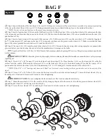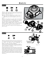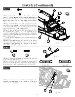
BAG G (Continued)
2 6
Figure 56
Table 55B
!
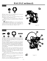
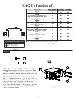
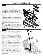
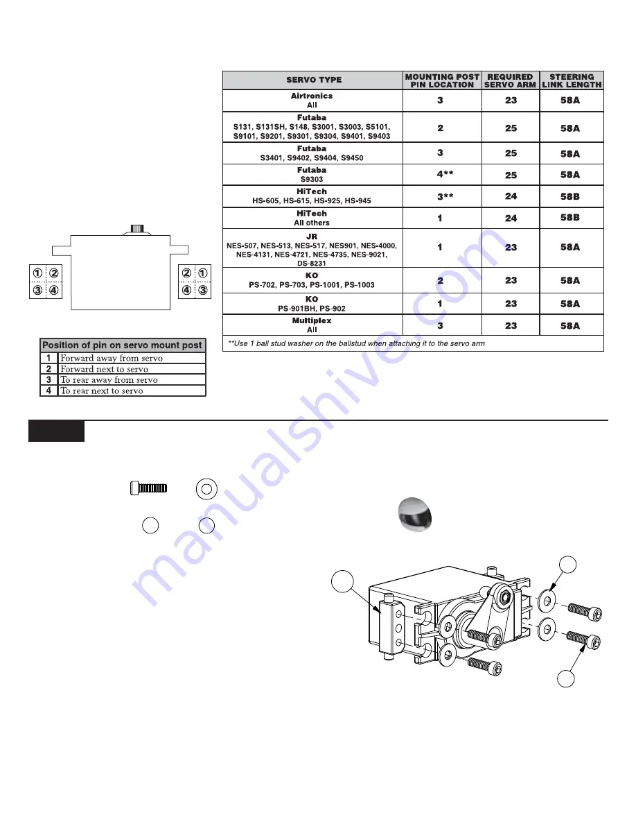
Step 9. Use Tables 55A and 55B to determine how the servo
mounting posts (146) should be attached to the servo
(not included)
.
!
Trim any flashing from the pins on the mounting posts so
that they will seat all the way into the holes in the chassis brace and
chassis.
!
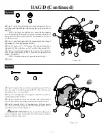
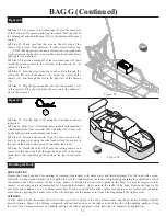
Step 10. Place a #4 washer (58) over each of the four
4-40 x 3/8" cap-head screws (17) and attach the servo posts (146)
to the servo by threading a screw (17) through the upper and
lower holes in each post (146). Do not tighten the screws (17)
yet! Just snug them up so that the posts are held in place, but can
still be moved from side to side with a little resistance. The screws
(17) will be tightened after the servo is installed so that the posts
(146) have the correct spacing.
Figure 56
58
17
*Note: Posts are not to scale.
Table 55A
146
58
17
Содержание XXX-T Matt Francis Edition
Страница 2: ......

