background image

3

Safety Instructions

CAUTION:

Read all of these Instructions.

Save these Instructions for later use.

Follow all Warnings and Instructions marked on the
audio equipment.

1) Read instructions

— All the safety and operating instructions

should be read before the product is operated.

2) Retain instructions 

— The safety and operating instructions should

be retained for future reference.

3) Heed Warnings

— All warnings on the product and in the operating

instructions should be adhered to.

4) Follow instructions 

— All operating and use instructions shoud be

followed.

5) Cleaning

— Unplug this product from the wall outlet before cleaning.

Do not use liquid cleaners or aerosol cleaners. Use a damp cloth for
cleaning.

6) Attachments

— Do not use attachments not recommended by the

product manufacturer as they may cause hazards.

7) Water and Moisture

— Do not use this product near water _ for

example, near a bath tub, wash bowl, kitchen sink, or laundry tub; in a wet
basement; or near a swimming pool; and the like.

8) Accessories

— Do not place this product on an unstable cart, stand,

tripod, bracket, or table. The product may fall, causing serious injury to a
child or adult, and serious damage to the product. Use only with a cart,
stand, tripod, bracket, or table recommended by the manufacturer, or sold
with the product. Any mounting of the product should follow the
manufacturer’s instructions, and should use a mounting accessory
recommended by the manufacturer.

9)

A product and cart combination should be moved with care. Quick

stops, excessive force, and uneven surfaces may cause the product and cart
combination to overturn.

10) Ventilation

— Slots and openings in the cabinet are provided for

ventilation and to ensure reliable operation of the product  and to protect it
from overheating, and these openings must not be blocked or  covered. The
openings should never be blocked by placing the product on a bed, sofa,
rug, or other similar surface. This product should not be placed in a built-in
installation such as a bookcase or rack unless proper ventilation is provided
or the manufacturer’s instructions have been adhered to.

11) Power Sources

— This product should be operated only from the

type of power source indicated on the marking label. If you are not sure of
the type of power supply to your home, consult your product dealer or local
power company. For products intended to operate from battery power, or
other sources, refer to the operating instructions.

12) Grounding or Polarization 

— This procuct may be equipped with

a polarized alternating-current line plug (a plug having one blade wider
than the other). This plug will fit into the power outlet only one way. This
is a safety feature. If you are unable to insert the plug fully into the outlet,
try reversing the plug. If the plug should still fail to fit, contact your
electrician to replace your obsolete outlet. Do not defeat the safety purpose
of the polarized plug.

13) Power-Cord Protection

— Power-supply cords shoud be routed so

that they are not likely to be walked on or pinched by items placed upon or
against them, paying particular attention to cords at plugs, convenience
receptacles, and the point where they exit from the product.

14) Outdoor Antenna Grounding 

— If an outside antenna or cable

system is connected to the product, be  sure the antenna or cable system is
grounded so as to provide some protection against voltage surges and built-
up static charges. Article 810 of the National Electrical Code, ANSI/NFPA
70, provides information with regard to proper grounding of the mast and
supporting structure, grounding of the lead-in wire to an antenna discharge
unit, size of grounding conductors, location of antenna-discharge unit,
connection to grounding electrodes, and requirements for the grounding
electrode.

"Note to CATV system installer:

This reminder is provided to call the CATV system installer’s attention to
Section 820-40 of the NEC which provides guidelines for proper grounding
and, in particular, specifies that the cable ground shall be connected to the
grounding system of the building, as close to the point of cable entry as
practical.

15) Lightning 

— For added protection for this product during a lightning

storm, or when it is left unattended and unused for long periods of time,
unplug it from the wall outlet and disconnect the antenna or cable system.
This will prevent damage to the product due to lightning and power-line
surges.

16) Power Lines 

— An outside antenna system should not be located in

the vicinity of overhead power lines or other electric light or power circuits,
or where it can fall into such power lines or circuits. When installing an
outside antenna system, extreme care should be taken to keep from
touching such power lines or circuits as contact with them might be fatal.

17) Overloading 

— Do not overload wall outlets, extension cords, or

integral convenience receptacles as this can result in risk of fire or electric
shock.

18) Object and Liquid Entry 

— Never push objects of any kind into

this product through openings as they may touch dangerous voltage points
or short-out parts that could result in a fire or electric shock. Never spill
liquid of any kind on the product.

19) Servicing

— Do not attempt to service this product yourself as

opening or removing covers may expose you to dangerous voltage or other
hazards. Refer all servicing to qualified service personnel.

20) Damage Requiring Service

— Unplug this product from the wall

outlet and refer servicing to qualified service personnel under the following
conditions:

a)

when the power-supply cord or plug is damaged.

b)

if liquid has been spilled, or objects have fallen into the product.

c)

if the product has been exposed to rain or water.

d)

if the product does not operate normally by following the operating

instructions. Adjust only those controls that are covered by the operating
instructions as an improper adjustment of other controls may result in
damage and will often require extensive work by a qualified technician to
restore the product to its normal operation.

e)

if the product has been dropped or damaged in any way.

f )

when the product exhibits a distinct change in performance _ this

indicates a need for service.

21) Replacement Parts 

— When replacement  parts are required, be

sure the service technician has used replacement parts specified by the
manufacturer or have the same characteristics as the original part.
Unauthorized substitutions may result in fire, electric shock, or other
hazards.

22) Safety Check

— Upon completion of any service or repairs to this

product, ask the service technician to perform safety checks to determine
that the product is in proper operating condition.

23) Wall or Ceiling Mouting 

— The product shoud be mounted to a

wall or ceiling only  as recommended by the manufacturer.

24) Heat

— The product should be situated away from heat sources such

as radiators, heat registers, stoves, or other products (including amplifiers)
that produce heat.

ANTENNA
LEAD IN
WIRE

ANTENNA
DISCHARGE UNIT
(NEC SECTION 810-20)

G

ROUNDING CONDUCTORS

(NEC SECTION 810-21)

GROUND CLAMPS

POWER SERVICE GROUNDING
ELECTRODE SYSTEM
(NEC ART 250. PART H)

NEC - NATIONAL ELECTRICAL CODE

ELECTRIC
SERVICE
EQUIPMENT

Example of Antenna Grounding as per

National Electrical Code, ANSI/NFPA 70

GROUND
CLAMP

All manuals and user guides at all-guides.com

Содержание Tascam Portastudio 424 MkIII

Страница 1: ...OWNER S MANUAL 424 3D0023100A All manuals and user guides at all guides com a l l g u i d e s c o m...

Страница 2: ...ion 41 Output section 41 424 MKIII Recorder Cassette loading and dbx system 42 Transport controls 43 Track controls 44 Displays 44 Autolocators 44 Optional Accessories 47 Care and Maintenance 48 49 Ho...

Страница 3: ...ucture grounding of the lead in wire to an antenna discharge unit size of grounding conductors location of antenna discharge unit connection to grounding electrodes and requirements for the grounding...

Страница 4: ...inadvertent connection to the mains supply If this product is not provided with a mains plug or one has to be fitted then follow the instructions given below IMPORTANT DO NOT make any connection to t...

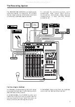
Страница 5: ...ack recorder Effects processors etc The Recording System The Three Steps to Multitrack In TRACKING and Overdubbing the mixer inputs are usually microphones or instruments going to different tracks of...

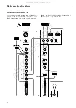
Страница 6: ...ain Mix The illustration below shows how input signals pass through the 424 MKIII Mixer section After the MASTER fader they go to the L R LINE OUT Signal Flow in the 424 MKIII Mixer Understanding the...

Страница 7: ...ockwise and the MONITOR LEVEL is turned up you can hear the tape playback in the headphones and MONITOR outputs You can adjust the monitor level of each track by adjusting its TAPE CUE control The cha...

Страница 8: ...the mixer has a stereo output however using the DIRECT feature you can record on any or all of the 4 tracks at one time For more details see Recording on More Than Two Tracks Simultaneously page 22 T...

Страница 9: ...n stereo cassette recorders Material recorded on the 424 MKIII must be mixed down to stereo for final distribution The 424 MKIII needs the entire width of the tape to record its four tracks eliminatin...

Страница 10: ...a cassette length that is as close as possible to the length of the program you plan to record Cassettes C 60 length and shorter are often made from thicker stock than longer cassettes The tape used...

Страница 11: ...m a point just after the channel fader TAPE CUE The EFFECT 2 controls can be switched to act as the TAPE CUE level controls by means of the correspondingly labeled switch and adjust the playback level...

Страница 12: ...1 or 2 point Pressing LOC for half a second or more allows you to check the memo point on the display REHEARSAL Lets you program a punch in out sequence to be used for rehearsals and for AUTO IN OUT A...

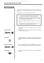
Страница 13: ...y The POWER switch is located on the back beside the power cable 4 Plug your headphones into the front PHONES jack so you can hear the input signal going to the mixer section of the 424 MKIII 5 Set th...

Страница 14: ...our voice in the left side of the headphones When using a line level source such as electronic instruments instead of the mic the TRIM does not need to be turned up very far if at all 16 As a trial le...

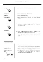
Страница 15: ...the mic You will see meter 1 move If no level or too low a level is shown continue to speak into the mic and slowly turn the channel 1 TRIM control to the right MIC until the meter peaks at no more th...

Страница 16: ...de the MONITOR SELECT LINE OUT switch to the center MONO position 3 Press the RTZ key The tape will rewind automatically stopping at the zero counter point 4 Press PLAY 5 Turn the MONITOR LEVEL contro...

Страница 17: ...Set the channel 1 INPUT selection switch to the left MIC LINE position 2 Turn the channel 1 PAN control all the way to the right R position 3 Bring the channel 1 fader to 7 4 Bring the MASTER fader t...

Страница 18: ...d 11 Press STOP to stop recording 12 The REC 2 indicator in the meter should now be blinking as before Set TRK 2 RECORD FUNCTION switch back to its SAFE position and the indicator will turn off Begin...

Страница 19: ...mixes will be recorded on Note that in this method the mixer channel number has nothing to do with what track the instrument winds up on Any mixer channel can be panned to any track These mixer channe...

Страница 20: ...channel as well as with channel 5 or 6 the signal level will be doubled as it is being mixed through two channels together Use the stereo channels 7 and 8 to add additional signal sources to the mix...

Страница 21: ...R fader to the shaded area between 7 and 8 3 Set the MONITOR SELECT LINE OUT switch to the L R position 4 Set all the INPUT select switches on the input channels to the right TAPE position 5 Press PLA...

Страница 22: ...nto Record mode then press PLAY on the 424 MKIII 14 When recording is done stop both machines rewind the mixdown tape and listen to it If the mixdown tape does not sound right make the necessary corre...

Страница 23: ...d down a new memory point is established and the previous memory point is erased MEMO points can t be entered while the tape is locating to either MEMO point or during REPEAT If the COUNTER RESET butt...

Страница 24: ...for 0 5 second or more autolocation does not start and only the tape counter shows the location point Hit the LOC 2 key to fast wind the tape to the MEMO 2 point Note For the deck to autolocate the c...

Страница 25: ...automatically rewind to the lower MEMO location and start over Press any transport keys except Play The function pressed will be activated If the tape is wound outside the repeat loop points the REPE...

Страница 26: ...on channel 2 until the MONITOR level meters read a maximum of from 0 to 3 and adjust the MONITOR LEVEL control for the desired headphone listening level 5 Play the instrument You ll hear it together w...

Страница 27: ...nch in The IN indicator will glow on the display and an LED will start flashing above the RECORD button The counter readout at which the key was pressed is stored as the PUNCH IN point 5 When the tape...

Страница 28: ...During the punch in setting or the rehearsal process if you press the footswitch after STOP the tape will rewind to your START point Rehearsal function is not available while the 424 MKIII is in the...

Страница 29: ...he memory points will be cleared and AUTO will turn off in the display The 424 MKIII lets you manually punch in too There are 2 ways to initiate the punch in recording The first is with the transport...

Страница 30: ...blinking and locate the tape to a point a little before the error then press PLAY 3 When you reach JUST BEFORE the error press the footswitch This has the same effect as pressing RECORD and the REC 2...

Страница 31: ...3 along with another live part onto track 4 for a total of four parts on one track Bouncing Tracks Ping Pong Ping pong procedure In this example we will combine material from tracks1 3 onto track 4 1...

Страница 32: ...n on solid and track 4 will record a copy of what is on tracks 1 3 9 You ll hear the mix being recorded on track 4 in the headphones 10 Once the recording is done press STOP 11 The REC 4 indicator wil...

Страница 33: ...eturns from the reverb unit In this method the stereo inputs function as effect returns Setting effect send levels Setting the output level of effect devices The goal is not to distort the device whil...

Страница 34: ...nput channel There s no law that says the output of an effects device must be plugged into a STEREO INPUT either They can also be plugged into LINE INPUTS just like any other source if you are cautiou...

Страница 35: ...are themselves a computer type digital language and cannot be recorded on analog tape it is necessary to convert them to recordable FSK Frequency Shift Keying signals using an appropriate converter su...

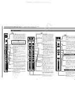
Страница 36: ...atures and Controls 40 7 INPUT select switches channels 1 4 This is used to control what the source of the channel is The left position MIC LINE is used when recording microphones instruments in track...

Страница 37: ...for MIDI virtual tracks you should probably set this switch to MON while recording tape tracks and L R on mixdown Stereo Input Section 18 MONITOR SELECT switches These switches determine what you will...

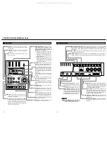
Страница 38: ...NR system provides a net noise reduction broadband not just hiss of about 30 dB and also permits a net gain in tape headroom of about 10 dB allowing recordings over a 90 dB dynamic range Cassette Loa...

Страница 39: ...tape at high speed in the forward direction 33 STOP key Stops any tape motion and disables all transport modes 34 PLAY key a Press this key alone to start playback b If pressed together with RECORD r...

Страница 40: ...switch This provides a playback loop or block repeat between MEMO 1 and MEMO 2 points Track Controls 38 RECORD FUNCTION switches 1 4 These switches put the respective tracks into Record Ready Recordi...

Страница 41: ...arting location Pressing RTZ 44 gets you back to that location 51 REHEARSAL switch Helps you rehearse a punch in without erasing anything until you are ready to actually record p 29 52 AUTO PUNCH swit...

Страница 42: ...f any excess cleaning fluid with a dry swab Even though the heads used in your 424 MKIII have high wear resistance and are rigidly constructed performance degradation or electro mechanical failure can...

Страница 43: ...g fluid onto the shaft Clean thoroughly and wipe off excess fluid Degaussing the Tape Path 1 Hold the degausser about 1 m 3 feet away from the recorder Turn it on slowly move in to the tape path Move...

Страница 44: ...vel 60 dBV 1mV MIC position 20 dBV 0 1 V LINE position Maximum Input Level 3 dBV 1 4 V at Trim Min MIC LINE INPUT Ch 1 6 1 4 phone jack x 6 Input Impedance 5 6k ohms Nominal Input Level 50 dBV 3mV MIC...

Страница 45: ...input level of 60 dBV 4 MIC INPUTS to LINE OUTPUT 60 dB at a nominal input level of 60 dBV 1 LINE INPUT to LINE OUTPUT 76 dB at a nominal input level of 10 dBV 4 LINE INPUTS to LINE OUTPUT 70 dB at a...

Страница 46: ...ion 22 W In these specifications 0 dBV is referenced to 1 Volt Actual voltage levels are also given in parentheses 0 316 V for 10 dBV rounded off to 0 3 V dbx is a registered trademark of dbx Incorpor...

Страница 47: ...54 53 Block Diagram All manuals and user guides at all guides com...

Страница 48: ...ts WD1 8YA U K Phone 01923 819699 TEAC DEUTSCHLAND GmbH Bahnstrasse 12 65205 Wiesbaden Erbenheim Germany Phone 0611 71580 TEAC FRANCE S A 17 Rue Alexis de Tocqueville CE 005 92182 Antony Cedex France...

Отзывы: